The 400 Hz medium frequency power supply is one of the reference power sources for military radars, avionics equipment and some armored vehicle equipment [1–2]. Its power quality level is related to the performance of weapon equipment. The main load of medium frequency power is motor load, and most of the operating conditions are Under an unbalanced load condition, the traditional intermediate frequency power supply has a weak unbalanced load, and the stability and reliability are poor. Therefore, it is very important to study the mid-frequency inverter power supply.
The three-phase four-leg inverter topology adds a fourth bridge arm on the basis of the traditional three-phase full-bridge inverter, connecting the neutral point of the three-phase load with the midpoint of the fourth bridge arm and passing the fourth bridge. The arm controls the voltage of the neutral point, so that the three-phase four-leg inverter can generate three-phase independent voltage, so that the inverter has the ability to stabilize the three-phase voltage symmetrical output. This inverter topology has the advantages of flexible control method, high DC voltage utilization, and no need to connect large DC capacitors. It avoids connecting transformers at the midpoint, greatly reducing the volume and weight of the inverter, and reducing the number of weapons systems and armored vehicles. With the limited volume of aviation platforms, it has received extensive attention and research.
Three-phase four-leg inverter topology modulation strategies include pulse width modulation [3], hysteresis current control [4], space vector pulse-width modulation (SVPWM) [5] and other strategies. Among them, SVPWM has the advantage of easy realization of digital control and high utilization of DC bus voltage, so it is mostly used in inverter modulation. The traditional SVPWM strategy [6-7] based on αβγ coordinate system requires repeated coordinate transformation of the three-phase voltage and current. The calculation process is complex, and the reference voltage must be determined according to the load condition. When the load is abrupt or unknown, the reference voltage is The trajectory cannot be determined, resulting in difficult real-time control. Literature [8] proposed a three-dimensional vector pulse width modulation technique based on the abc natural coordinate system. The calculation method is simple and can be extended to multi-level three-phase four-leg inverters, but the reference voltage is calculated. The method has not been given yet.
Based on the SVPWM technology of the natural coordinate system, this paper studies the modulation strategy of the three-phase four-leg inverter. By establishing the average current model of the four-arm topology, the reference voltage is determined, and the reference voltage is calculated according to the principle of “volt-second balanceâ€. Duty cycle. Since the reference voltage is calculated in real time according to the load current, the three-phase symmetrical voltage of the three-phase unbalanced load can be output, and the total harmonic distortion is small, which is verified by simulation and experiments.
1
Theoretical Analysis Based on Natural Coordinate System SVPWM
1.1 Synthesis and Selection of Space Vectors and Voltage Vectors
Figure 1 shows the main circuit topology of a three-phase four-leg inverter.
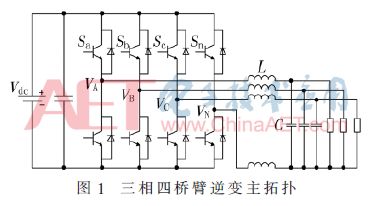
The main topology has four pairs of bridge arms. Each pair of bridge arms corresponds to two switch states, which collectively constitute 24=16 kinds of switch combinations. The switch state of each bridge arm is represented by the switch vector Si:

In the above equations, i=a, b, c, n denote the A, B, C, and N phases of the inverter, respectively. It should be noted that the upper and lower switching devices of the same bridge arm cannot be turned on at the same time; otherwise, the bridge arm straight-through phenomenon will occur and the switching devices will be damaged. According to the switch state can get the voltage vector:

Combining Equation (1), the correspondence between 16 combinations of switching states of the inverter and the space voltage vector can be obtained, as shown in Table 1.
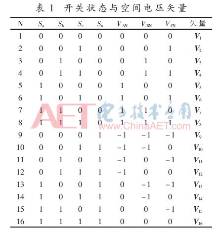
The 16 switching states in Table 1 correspond to the space voltage vector depicted in the abc natural coordinate system, and can be obtained as the space voltage vector diagram in FIG. 2 .
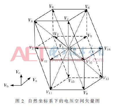
Figure 2 can be viewed as a closed dodecahedron. The dodecahedron can be segmented by using planes Va = 0, Vb = 0, Vc = 0, and Va - Vb = 0, Va - Vc = 0, and Vb - Vc = 0. Twenty-four spatial tetrahedrons, each consisting of two zero-voltage vectors (V1, V16) and three non-zero voltage vectors. As long as it is determined in which tetrahedron the reference voltage vector Vref falls, it can be synthesized with the corresponding space voltage vector.
In order to judge that the reference voltage vector falls in a certain tetrahedron, this vector is performed with six planes of Va=0, Vb=0, Vc=0, and Va-Vb=0, Va-Vc=0, Vb-Vc=0. In comparison, the tetrahedron of the synthesized reference voltage vector is determined by judging the comparison result. Using the binary counting method, the six comparison results are weighted to mark the tetrahedron, which is defined as follows:
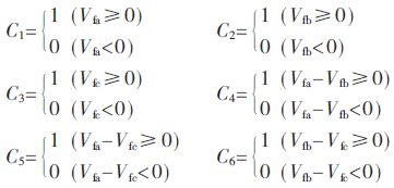
Where Vfa, Vfb, and Vfc are normalized to the natural coordinate system abc in the reference voltage vector Vref. The expression of the pointer function is:

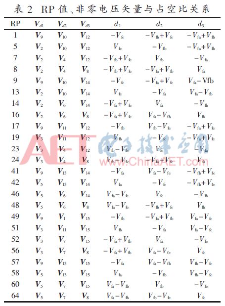
The RP value calculated by Equation (2) is shown in Table 2, which corresponds to twenty-four tetrahedra. The RP value determines the tetrahedron where the reference voltage vector is located, and the non-zero vector of the tetrahedron and the zero-vector synthesis reference voltage vector are selected.
1.2 Calculation of Duty Cycle of Voltage Vector
The reference voltage vector is composed of non-zero vectors and zero vectors. The action time of the switching voltage vector can be obtained according to the principle of "Volt-second balance":

In the above equation, Vd1, Vd2, and Vd3 are non-zero switching vectors corresponding to d1, d2, and d3, and the subscripts a, b, and c respectively represent the projection values ​​of the switching vector on the abc coordinate axis. When the value of RP is determined, the synthesized space vector and duty cycle can be obtained based on the reference voltage. The specific results are shown in Table 2.
From Table 2, it can be seen that the strategy of determining the space tetrahedron, the switching voltage vector, and the duty ratio by calculating the RP value is simpler than the calculation of the duty ratio in the αβγ coordinate system, and is easy to realize the digital control technology.
1.3 Calculation of Reference Voltage Vectors
The average current model of the three-phase four-leg inverter in the abc coordinate system is established [9]. As shown in Figure 3, the output voltage is equivalent to a controlled voltage source.
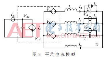
IA, IB, and IC are three-phase load currents that are equivalent to current sources and can be decomposed into positive sequence Ip, negative sequence In, and zero sequence I0 components according to the symmetrical component method. The lower scale p, n, and 0 represent the positive sequence, respectively. Negative sequence and zero sequence.

And the three-phase voltage and current are symmetrically output. VM represents the rated value of the output voltage, and the three-phase voltage expression is:


Since the three-phase voltage equivalent diagram is the same, symmetrical components are analyzed with phase A. Figure 4 shows the positive sequence, negative sequence, and zero sequence component equivalents of Phase A.
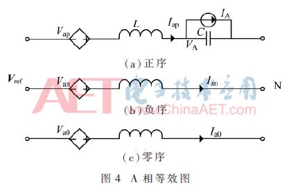
According to circuit theory, the positive, negative and zero sequence components of the reference voltage vector Vref can be represented as:
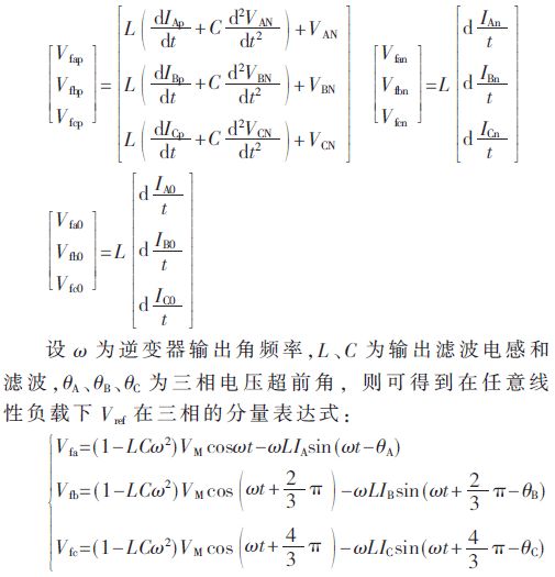
Analysis shows that as long as the three-phase load current is detected, the reference voltage can be obtained. When the load changes, DSP can calculate the reference voltage of each phase according to the change of the load current, so as to control the symmetrical output of the three-phase voltage.
2
Simulation analysis
In order to verify the feasibility and effectiveness of the SVPWM strategy based on natural coordinate system, the simulation circuit MATLAB/Simulink was used to establish a three-phase four-leg inverter simulation circuit based on the SVPWM strategy. The specific simulation parameters were as follows: the designed total output power was 6 kV. A, DC input voltage 300 V, power device switching frequency is 20 kHz, the output three-phase voltage is 115 V, the frequency is 400 Hz, the output filter circuit filter inductor 1 mH, filter capacitor 20 μF.
The simulation analysis of the inverter is mainly carried out under the following load conditions: (1) resistively unbalanced load; (2) resistive and capacitive resistance unbalanced load.
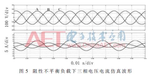
The three-phase resistive unbalanced loads are 13 Ω, 26 Ω, and 40 Ω, respectively. The simulation results of the three-phase voltage and current of the inverter are shown in Figure 5.
Inverter with three-phase resistive and capacitive impedance unbalanced loads, including phase 13 Ω and 10 mH inductive loads, phase 13 pure resistive load 13 Ω, C phase 13 Ω and 10 μF capacitive load, simulation results such as Figure 6 shows.
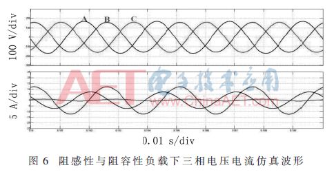
Analysing the simulation results, we can see that the three-phase four-leg inverter based on the natural coordinate system SVPWM strategy under unbalanced load conditions, the three-phase output voltage waveform is more symmetrical, and after the simulation system FFT analysis of the three-phase voltage waveform harmonic The wave distortion ratio THD is less than 3%.
3
Experimental results
In order to verify the feasibility of the scheme, an experimental prototype was designed. The vector control of the power device was completed based on DSP (TMS320F28069). The main parameters of the experimental prototype were: output power 6 kV·A, input DC bus voltage 300 V, the output voltage rms and frequency is 115 V/400 Hz, the switching frequency is 20 kHz, and the output filter's inductance and capacitance are 1 mH and 20 μF, respectively. Mainly tested the output capacity of the inverter under unbalanced load and recorded the three-phase voltage current and neutral current waveform under unbalanced load.
Figure 7 shows the three-phase unbalanced resistance and resistance capacitive load, the three-phase voltage and the A-phase current waveform. It can be seen that the inverter output has strong adaptability and can make three phases under various unbalanced load conditions. Voltage symmetrical output.
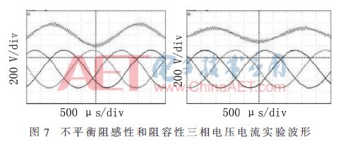
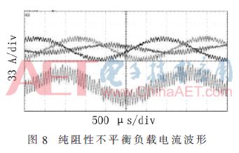
Figure 8 shows the three-phase filtering and midline inductor current under pure resistive 1/3 unbalanced load. Since the inductance affects the current with a small ripple, the midline current ripple is more obvious, but the voltage waveform still satisfies THD<3%.
4
in conclusion
Based on the SVPWM strategy of the abc natural coordinate system, the three-phase four-leg mid-frequency inverter is compared with the space-vector modulation of the αβγ coordinate system. On the one hand, the complicated coordinate transformation is omitted, and on the other hand, the selection and switching of the space tetrahedron is performed. The calculation of the duty cycle of the vector is also simpler, and it is easy to implement the digital control and DSP programming. In this paper, the average current model of three-phase four-leg arm is established. The calculation method of spatial reference voltage is analyzed and given. Finally, the simulation and experiment verify that the SVPWM strategy of the IF inverter has three-phase stability under unbalanced and nonlinear loads. Symmetric output capability has a certain practical value.
Aluminum Cell Phone Stand, Durable Cellphone,Desk Cell Phone Stand Holder Aluminum Phone Dock Cradle,etc.
Shenzhen Chengrong Technology Co.ltd is a high-quality enterprise specializing in metal stamping and CNC production for 12 years. The company mainly aims at the R&D, production and sales of Notebook Laptop Stands and Mobile Phone Stands. From the mold design and processing to machining and product surface oxidation, spraying treatment etc ,integration can fully meet the various processing needs of customers. Have a complete and scientific quality management system, strength and product quality are recognized and trusted by the industry, to meet changing economic and social needs .

Aluminum Vell Phone Stand,Aluminum Cell Phone Desk Stand,Cell Phone Holder For Stand,Cell Phone Stands
Shenzhen ChengRong Technology Co.,Ltd. , https://www.laptopstandsupplier.com
