In recent years, people have demanded the high level of intelligence, safety, and infotainment. The automotive electronics industry has also continued to develop at a high speed. At present, the ratio of automotive electronics to automotive costs is approximately 40% to 60%. Electronic control systems and on-board electronic control devices continue to be incorporated into automotive design architectures, including various sensor module units such as sensors for temperature, wheel speed, rotation angle and acceleration, equipped with electric assisted steering and electronic parking brake systems, continuously satisfying The comfortable ride and safety requirements of our drivers and passengers.
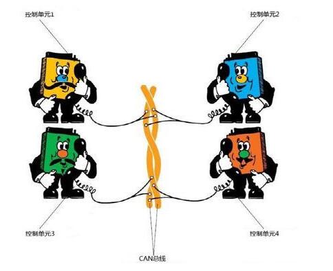
Among these numerous automotive electronic systems, the vehicle controller LAN interface (CAN Bus) can be connected in series or in parallel with any node device due to the two-wire serial topology, which not only enables wiring and maintenance. The complexity is greatly reduced, and the wire and cabling costs can be reduced at the same time, making it the preferred vehicle system transmission interface.

The two-wire differential transmission technology used in the CAN Bus transmission interface can reduce the signal to a single-line signal transmission mode if a differential signal line cannot transmit signals because of a disconnection or grounding fault. The probability of poor communication in the vehicle system not only improves the stability of the body functions, but also the differential twisted pair connection has the ability to resist common mode electromagnetic interference. In addition, the CAN Bus uses a multi-host architecture to transmit and receive signals. Each host can actively send communications to a specific node. Therefore, it can maintain the maximum space on-line to cope with the huge amount of data transmission and reception, which not only enriches the body functions. If any host node fails, it will not be affected. It will ensure the driver's driving experience and reduce the risk of faulty maintenance.
CAN Bus's transmission speed can have different choices. Currently, the highest application requirement is 1Mbps, and its transmission distance is as far as 1000M. Therefore, it can meet the requirements of different subsystems in the car for different transmission speeds and transmission distances. Under the consideration of costs, body weight, and specification characteristics during the development phase, the CAN Bus interface can meet the above requirements, so that about 70% of the vehicles at this stage have adopted the CAN Bus as their transmission interface yesterday.
As an automobile environment that is frequently in contact with the human body, electrostatic discharge events (ESD), electrical overload events (EOS), and electrical fast transient events (EFT) often occur during the running of a car, which is a problem for a moving car. Potential threats, and the CAN transceiver chip will be considered in the design of some static immunity, but the level is far from the requirements of system-level testing, so the protection design for the CAN communication interface becomes very important.
At present, the standards of automotive electronics related to EMC testing are mainly divided into two categories:
1: Conduction transient test for power supply
2: Electrostatic and surge tests for communication interfaces
For the power supply test, Pulse 1(a) simulates the transient event caused by the inductive load due to the power cutoff. Pulse 2(a) simulates the inductive load of the beamline due to the momentary moment of the current burst. Pulse 2(b) simulates the blower or The wiper motor is driven by the momentary power supply removal. Pulse 3(a)(b) simulates the momentary wave generated by the switching process and the load-blow-up transient of the pulse 5 battery.
This article mainly introduces the static and surge test of the CAN interface.
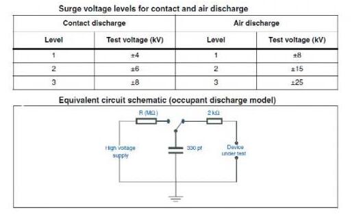
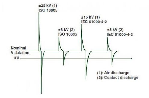
Electrostatic test standards generally have the IEC61000-4-2 set by the International Electrotechnical Commission and the ISO10605 standard set by the International Organization for Standardization. These two test models are similar in that the capacitance values ​​of the internal generators are different, and the automotive-grade product regulations The need to meet the ISO10605 air 25KV test requirements.


As shown in the figure, leiditech lists the energy levels of each test level in the two standards. Therefore, the 25KV electrostatic discharge capability of automotive products is much stricter than the 15KV test specified by IEC.
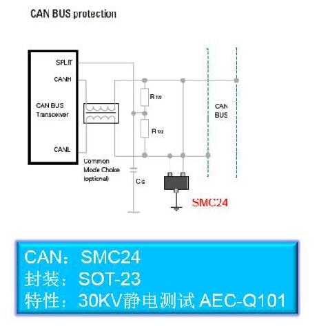
To protect the CAN transceiver from the adverse transient voltages such as the ISO10605 ESD mentioned above, a TVS diode can be placed on the bus lines CANH and CANL. This TVS diode acts as a clamping circuit and directs any occurring high-energy pulses to ground, away from the transceiver. When choosing a diode, it is important to note that according to the design requirements, the diode's rating is expected to reach the desired energy level.

The leiditech SMC24 is a two-way 24V protection package in the SOT23 package.
Low capacitance products can meet CAN signal speeds up to 2Mbit/s without packet loss;
The low clamping voltage also ensures that the back-end chip experiences less surge pressure when a transient surge occurs.
ESD protection class up to IEC61000-4-2 contact discharge and air gap discharge 30kV, and EFT protection class up to IEC61000-4-4 4kV, and passed AECQ101 car gauge reliability verification to ensure that the operating temperature from low temperature -55 degrees C To 125 °C high temperature, in order to ensure the car body in the harsh high-temperature operating environment applications.
ESD device layout recommendations
a) Place the device as close to the input or connector as possible.
b) Minimize the path length between the equipment and the protected line.
c) Keep parallel signal paths to a minimum.
d) Avoid operating the protected conductor in parallel with the unprotected conductor.
e) Minimize all printed circuit board (PCB) conductive loops, including power and ground loops.
f) Minimize the transient return path length to ground.
g) Avoid using a shared transient return path to a common ground.
h) Use ground planes, multilayer printed circuit boards, and ground vias as much as possible.
Opzv Battery,Opzv1000 2V1000Ah Solar Battery,Solar Batteries 2V Opzv,Deep Cycle Battery 2V 1000Ah
Jiangsu Stark New Energy Co.,Ltd , https://www.stark-newenergy.com
