I. Review of Magnetic Current Saturation in Electromagnetic Current Transformers
1, magnetic saturation
The so-called magnetic saturation means that the magnetic flux density in the magnetic current transformer core is greater than the saturation magnetic flux density, and the magnetic flux density is no longer increased by the increase of the primary current.
2, magnetic saturation
Magnetic flux density is an alternating variable. When no magnetic saturation occurs, the maximum magnetic flux density of the transformer core is: Bm=E2/(4.44*f*N2*S)
In the formula, E2 is the secondary winding induced electromotive force, approximately equal to the secondary winding output voltage. N2 is the number of turns of the secondary winding and S is the cross-sectional area of ​​the core. For fixed transformers, N2 and S are constant values.
Therefore, the core flux density is proportional to the secondary voltage and inversely proportional to the current frequency.
The secondary voltage is determined by the secondary current and the secondary load. It can be seen that the magnetic saturation causes of the electromagnetic current transformer include:
A, a large current, greater than the rated current;
B, the secondary load is too large, greater than the rated secondary load;
C, the current frequency is too low, less than the rated frequency.
3, magnetic saturation hazard
After magnetic saturation occurs in the current transformer, the primary current is no longer proportional to the secondary current, and the current transformer cannot perform normal measurement or protection, causing a safety accident. In addition, in the magnetic saturation state, the magnetic flux density in the iron core is large, the eddy current loss and the hysteresis loss are large, and the iron core generates heat, which easily damages the transformer.
Second, the Hall current sensor works
Hall current sensors are divided into open-loop Hall current sensors and closed-loop Hall current sensors according to different operating principles.
1, open-loop Hall current sensor working principle
Open-loop Hall current sensors are also known as: direct-type Hall current sensors, direct-detection Hall current sensors.
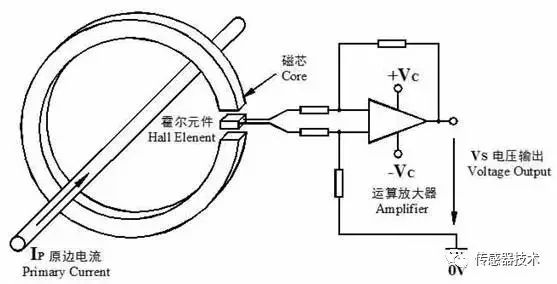
As shown in Figure 1, an open-loop Hall current sensor consists of a magnetic core, a Hall element, and an amplifier circuit. The magnetic core has an open air gap, and the Hall element is placed in the air gap. When the primary conductor flows through the current, a magnetic field having a magnetic field strength proportional to the current is generated around the conductor. The magnetic core collects the magnetic flux at the air gap. The Hall element outputs a voltage signal proportional to the magnetic induction at the air gap, and the amplified signal is amplified. The circuit amplifies and outputs the signal. This type of sensor usually outputs a voltage signal of about ±10V. Some sensors are also converted to current signal output in order to enhance electromagnetic compatibility.

Figure 1 Open Loop Hall Current Sensor Operation
2, closed-loop Hall current sensor working principle
Closed-loop Hall current sensors are also called: zero-flux Hall current sensors, zero flux transformers, magnetic balance Hall current sensors.
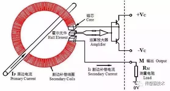
As shown in Figure 2, a closed loop Hall current sensor includes a magnetic core, a Hall element, an amplifying circuit, and a secondary compensation winding. Compared with the open loop Hall current sensor, the closed loop Hall current sensor has more secondary compensation windings, and it is the secondary compensation winding that greatly improves the performance of the closed loop Hall current sensor.

Figure 2 working principle of the closed-loop Hall current sensor
The amplifying circuit accepts the output of the Hall element and amplifies the current signal to the secondary compensation winding. The magnetic field generated by the secondary compensation winding in the magnetic core and the magnetic field generated by the primary current are equal to each other at the air gap, and the directions are opposite. The primary magnetic field forms a negative feedback closed-loop control circuit.
If the secondary current is too small, the generated magnetic field is insufficient to cancel the primary magnetic field, and the amplifying circuit will output a larger current. On the contrary, the output current of the amplifying circuit decreases, so as to maintain the magnetic field balance at the air gap.
If the primary current changes, the magnetic field balance at the air gap is destroyed, and the negative feedback closed-loop control circuit also adjusts the secondary output circuit to rebalance the magnetic field.
Macroscopically speaking, the zero-flux will remain at the air gap and maintain magnetic balance. This is also the reason for the names of zero-flux transformers and magnetic balance Hall current sensors.
3, the main difference between closed loop Hall current sensor and open loop Hall current sensor
A, bandwidth difference
Microscopically speaking, the magnetic field at the air gap always changes near zero flux. Since the magnetic field changes very little and the change range is small, the changing frequency can be faster. Therefore, the closed-loop Hall current sensor has a fast response time. The actual closed-loop Hall current sensor bandwidth can usually reach more than 100kHz. However, the open-loop Hall current sensor usually has a narrow bandwidth. For example, the bandwidth of the LEM's HAZ series open-loop Hall current sensor is about 3 kHz.
B, accuracy difference
The open-loop Hall current sensor secondary output is proportional to the magnetic induction at the core air gap, and the magnetic core is made of a highly magnetically permeable material. Non-linearity and hysteresis are inherent characteristics of all highly magnetically permeable materials. Therefore, the open-loop Hall-effect sensor generally has a linearity angle difference, and the primary-side signal will have different secondary output during rising and falling. Open-loop Hall current sensors are usually less than 1% accurate.
Closed-loop Hall-effect current sensors work in a state of zero-flux, and the nonlinearity and hysteresis of the magnetic core do not affect the output, resulting in better linearity and higher accuracy. Closed-loop Hall current sensors typically reach 0.2% accuracy.
Second, Hall current sensor magnetic saturation problem
Many manufacturers of Hall current sensors will also advertise their non-magnetic saturation as an important advantage of Hall current sensors in their technical data. The magnetic saturation of the Hall current sensor is almost one of the main advantages of the Hall current sensor since its application.
Is this not the case?
In fact, the Hall current sensor contains a non-linear magnetic core, and it has been determined that the Hall current sensor will be subject to magnetic saturation under certain conditions!
1. Magnetic Saturation of Open Loop Hall Current Sensors
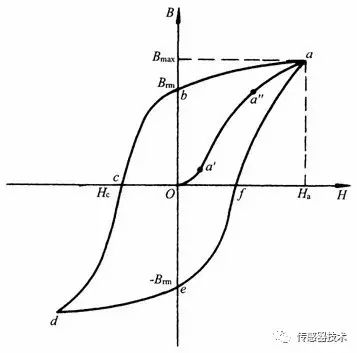
The following figure shows a typical magnetization curve for all highly magnetic materials:

Figure 3 Magnetization Curve of Hall Current Sensor Core
In the figure, Oa' is the initial non-linear segment, a'a'' is the linear segment, and a''a is the saturation region. In order to obtain better measurement results, both the open-loop Hall current sensor and the electromagnetic transformer will use a section with a good linearity in the magnetization curve as a working interval. In other words, as long as the magnetic induction intensity exceeds a certain range in the linear region, magnetic saturation occurs.
Compared with electromagnetic transformers, there is only one cause of magnetic saturation in an open-loop Hall-effect sensor, that is, the primary current is large enough.
Magnetic saturation is not caused by a low current frequency, which is an advantage of a Hall current sensor, and is also a magnetic saturation characteristic of an open-loop Hall current sensor.
In contrast, electromagnetic transformers also have the advantage that the secondary load is sufficiently small that magnetic saturation does not occur even if the overload is high.
2. Magnetic saturation of closed-loop Hall current sensor
Open-loop Hall current sensor magnetic saturation problem is relatively simple, in contrast, closed-loop Hall current sensor magnetic saturation problem seems incomprehensible, because the closed-loop Hall current sensor is working, the magnetic flux in the core is zero With zero magnetic flux, it will not naturally saturate.
However, this will only be under normal working conditions!
In fact, even if the magnetic saturation problems of electromagnetic current transformers or open-loop Hall current sensors occur under abnormal working conditions such as overload, low frequency, and excessive load, they will not occur under normal operating conditions. Magnetic saturation!
From the working principle of the closed loop Hall current sensor, zero magnetic flux is established on the premise that the magnetic field generated by the secondary compensation winding can cancel the magnetic field generated by the primary conductor. So, can this zero magnetic flux be maintained when the closed-loop Hall current sensor is not under any circumstances?
Obviously not!
A. When the sensor is not powered, the secondary compensation winding does not generate current. At this time, the closed-loop Hall current sensor is equivalent to an open-loop Hall current sensor. As long as the primary current is large enough, magnetic saturation will occur.
B, normal power supply, the original side of the current is too large. This is because the current that can be generated by the secondary compensation winding is limited, and when the magnetic field generated by the primary current is larger than the maximum magnetic field that can be produced by the secondary compensation winding, the magnetic balance is broken and the magnetic field in the magnetic core passes through. When the current continues to increase, the magnetic field in the magnetic core also increases. When the primary current is large enough, the closed-loop Hall current sensor enters the magnetic saturation state!
Compared with electromagnetic current transformers and open-loop Hall current sensors, the magnetic saturation of closed-loop Hall current sensors is not easy to occur, but it does not mean that it will not occur. Magnetic saturation can also occur if it is used improperly or over a long period of time.
Brake Disc For CHERY
Chery Brake Disc,Chery Auto Brake Disc,Chery Car Brake Disc,Chery Automobile Brake Disc
Zhoushan Shenying Filter Manufacture Co., Ltd. , https://www.renkenfilter.com
