The 5G mobile network and the Internet of Things (IoT) are two hot topics in the RF and microwave industry. In order to make new advances in such wireless applications, it is necessary to significantly increase the data transmission rate. At the same time, it needs to use acTIve electronically scanned arrays (abbreviated as AESA), phased array antennas, and multiple input multiple output ( The mulTIple-input-mulTIple-output (MIMO) technology has achieved major breakthroughs. In the prototype design and manufacturing process of the above application, it is very important to shorten the time and reduce the cost. With simulation and App, we can shorten the development cycle of wireless communication design.
Advanced Computing Resources Used in the Design of 5G Phased Array Antennas
As we discussed in previous blog posts, there are many improvements and design considerations that need to be made to implement the 5G mobile network. One of the directions of improvement for RF engineers is to increase the antenna gain to provide higher frequencies for 5G operation.
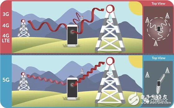
An isotropic, low-gain antenna for early networks vs. a 5G directional high-gain antenna.
Another requirement of the 5G mobile network is the improvement of phase advance technology. This technology can be used to form a radiation pattern and guide the direction of the antenna array beam to control the input signal, thereby solving the coverage angle problem.
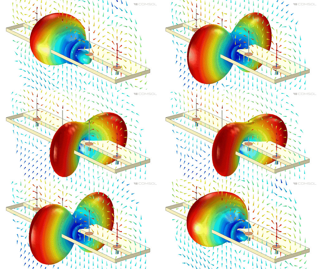
The monopole phased antenna array can direct the radio waves in a specified direction.
At the design stage, a device called a slot-coupled microstrip patch antenna array can be used to solve such coverage angle problems. However, in order to develop a device that optimizes the performance of 5G wireless communications, many more complex design parameters need to be considered.
It is often difficult to evaluate and apply physical effects (such as extreme temperature changes, structural deformation, and chemical reactions) through physical prototypes in design laboratories, but simulations can do the job. Unfortunately, not every design engineer is a simulation professional. This requires that any time an antenna array design or simulation environment changes, simulation professionals must participate in every step of the design process.
The App Developer solves this type of problem by further extending simulation capabilities. Now, a complex and cumbersome RF design numerical model can be converted into a user-friendly interactive tool that can be easily used by both professional and end users. Today, let us discuss the application of the slot-coupled microstrip antenna array synthesizer simulation app to understand how it helps us to optimize the phased array antenna design for 5G and IoT.
Slot-Coupled Microstrip Patch Antenna Array Synthesizer App
Active electronic scanning arrays, also known as phased antenna arrays, are commonly used in military applications such as radar and satellites. Nowadays, with the ever-increasing demands on the data transmission rate of communication devices, such arrays have a new application field - commercial applications. In this kind of equipment, the size of a simple component can easily exceed several dozen times of the wavelength, which results in the simulation design taking up a lot of memory. The result is that even if we only get the approximate value used to evaluate the conceptual model, it will take a considerable amount of computing time. Faster prototyping helps to quickly analyze performance and determine design parameters.
The slot-coupled microstrip patch antenna array synthesizer is based on a full finite element method (FEM) model of a single microstrip patch antenna, and is a low-temperature cofired ceramic (LTCC). ) Made on the substrate. The initial operating frequency of the device is 30 GHz, and the integration of the radiation pattern with the directional analysis of the entire array structure is done using COMSOL MulTIphysics and its powerful post-processing functions. The App Builder is a shortcut that provides a variety of ways to design and build a user-friendly graphical user interface (GUI) that converts common mathematical models into intuitive simulation tools.
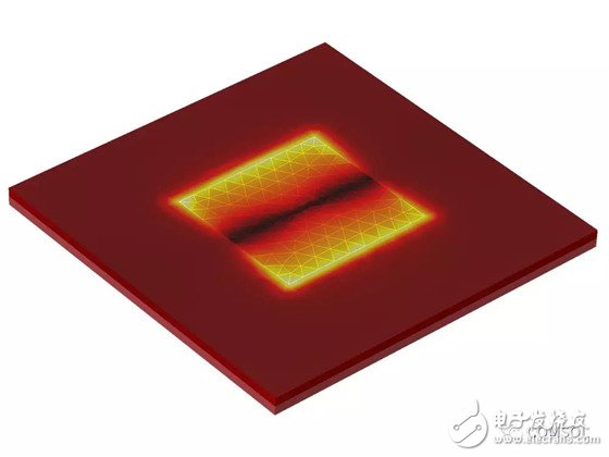
Top view of a slotted microstrip patch antenna.
The App Builder provides two necessary tools for creating an App: a form editor and a method editor. With the form editor, we can add form objects to the custom interface to make the GUI simple. The method editor helps us perform more advanced customization than form objects. After accurate simulation of a single microstrip patch antenna, we found a two-dimensional antenna array factor

The two-dimensional array factor corresponds to user input such as array size, phase, etc., difference series and angular resolution, and they are applied to radiation pattern data (emw.normEfar) of a single antenna.
The method editor is not only suitable for simple simulation of the visualization of predefined post-processing variables, but also for further customization.
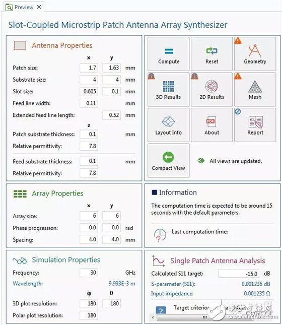
A preview of the main form used to display the form object.
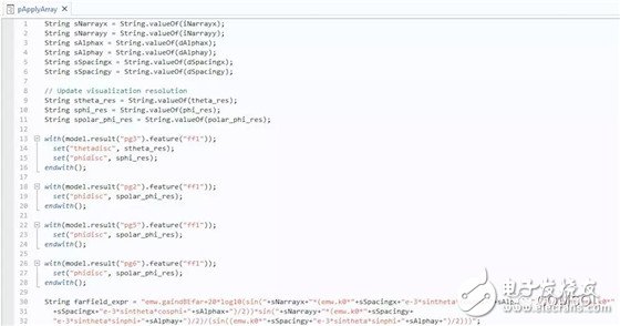
Use the Method Editor to create custom actions on form objects.
In this app, there are many design parameters that can be used to test the design of a microstrip patch antenna array, including:
Antenna properties
Patch size
Substrate size
Gap size
Feeder width
Extended feeder length
Patch substrate thickness and relative permittivity
Feeder substrate thickness and relative permittivity
Array properties
Array size
Phase advancement
spacing
Simulation properties
frequency
wavelength
3D coordinate drawing resolution
Polar plot resolution
The array dimensions, phase advance and spacing, and the distance between each unit are primarily used to characterize the shape and orientation of the antenna array radiation pattern. The angular resolution improves the visualization of 3D and 2D radiation patterns. Please note that when the antenna directivity is high, a higher resolution helps to accurately depict the side lobes.
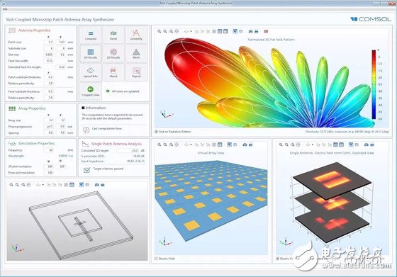
"Slot-Coupled Microstrip Patch Antenna Array Synthesizer" App's graphical user interface.
After the analysis is completed, the App compares the single antenna design parameter calculated by S parameter (S11) with the “pass/fail†criteria before the user runs the simulation and reports whether it is the best parameter. The App plots the electric field distribution on each dielectric layer and metal layer and visualizes the entire view of the array, giving App users a more intuitive experience of design performance. You can also choose to generate a complete simulation results report and detailed App usage instructions.
Simulation App offers endless possibilities for the presentation of numerical models
With the App Builder, you have unlimited ways to turn your model into a custom tool, but what can you do next? You can use the COMSOL Multiphysics® software to launch and use the Simulation App. As long as you are connected to the Internet, you can use a common web browser to run the app, and you can even deploy the app to colleagues or customers through the COMSOL ServerTM product.
In the “case downloadâ€, there are more apps in the physical fields of electrical, mechanics, fluids, and chemistry waiting for you to download and research. These demo apps can guide you through creating your own, useful apps.
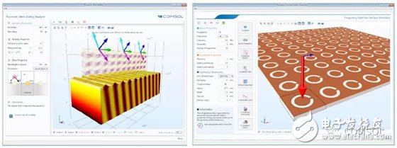
Periodically Complementary Open-Loop Resonator with Frequency Selection Plan "Demonstration App (right) and "Surface Plasmon Line Grating Simulator" Demo App (left).
Regardless of whether you are developing a simulation app for enhanced RF design for 5G networks or research in other application areas, start developing simulation apps today to optimize design workflows and product performance!
Usb Cables,Usb Wires,Usb Wire,Micro Usb Cable
UCOAX , https://www.ucoax.com
