The bandwidth of 5G needs to increase from the current 20MHz bandwidth to 100MHz or higher, which means that it needs to enter the frequency band above 3.6GHz or higher. To meet this need, Linear Technology's LTC5593 dual passive downconverter provides excellent linearity and dynamic range performance at 3.6GHz while supporting flat signal bandwidths in excess of 200MHz for extremely robust MIMO (Multiple Input Multiple Output) Receiver.
introductionIncreasing data transfer rates are a global demand that has surpassed the limits of current 4G wireless network capacity. The next generation of 5G networks needs to increase capacity by more than 10 times to keep up with future development needs. Although the 5G standard has not yet been finalized, most, if not all, market participants believe that bandwidth needs to increase at least (from the current 20MHz bandwidth) to 100MHz, and some even say it will increase to 200MHz. If so, you need to enter a frequency band above 3.6 GHz or higher.
To meet this need, Linear Technology's LTC5593 dual passive downconverting mixer delivers excellent linearity and dynamic range performance at 3.6 GHz while supporting flat signal bandwidths in excess of 200 MHz for robust MIMO ( Multiple input multiple output) Receiver. In systems such as Wi-Fi and 4G networks, MIMO technology has significantly improved the net swallow rate and receive rate of data when bandwidth is limited, so MIMO technology has proven its usefulness. When the 5G system migrates to higher frequency bands, the LTC5593 provides continuous 50Ω matching from 2.3GHz to 4.5GHz, supporting multi-band receivers in the 2.6GHz and 3.6GHz bands. For lower frequency bands, Linear Technology also offers other pin-compatible mixers, including the LTC5590, LTC5591, and LTC5592, which cover all of the remaining LTE receivers. The frequency coverage and typical 3.3V performance of each mixer are shown in Table 1. These mixers offer high conversion gain, low noise figure (NF), and high linearity and low DC power. The typical power conversion gain is 8dB with an input third-order intercept point (IIP3) of 26dBm, a noise figure of 10dB, and a power consumption of 1.3W.

The LTC5593 family of dual high performance mixers is ideal for wireless infrastructure MIMO receivers such as RRH (Remote Radio Head). Extremely compact, these systems are sealed and weather-proof and self-contained, making them challenging to maintain small size and thermal management when using a large number of electronic devices. The dual channel solution reduces the number of components required, simplifies LO signal routing and reduces board area. In addition, each LTC5593 includes integrated RF and LO baluns, double balanced mixers, LO buffer amplifiers, and differential IF amplifiers to further reduce overall solution size, complexity and cost .
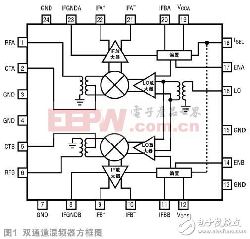
1 Mixer DescriptionThe simplified block diagram in Figure 1 shows a dual-channel mixer topology that uses a passive double-balanced mixer core to drive the IF output amplifier. The mixer core is a four-way switching MOSFET that typically has a conversion loss of approximately 7dB. In this case, however, the on-chip IF amplifier gain behind it greatly compensates for this loss, resulting in a total power gain of around 8 dB. The differential IF output is optimized for a standard 200Ω interface that directly drives the differential IF filter and variable gain amplifier, minimizing external components.
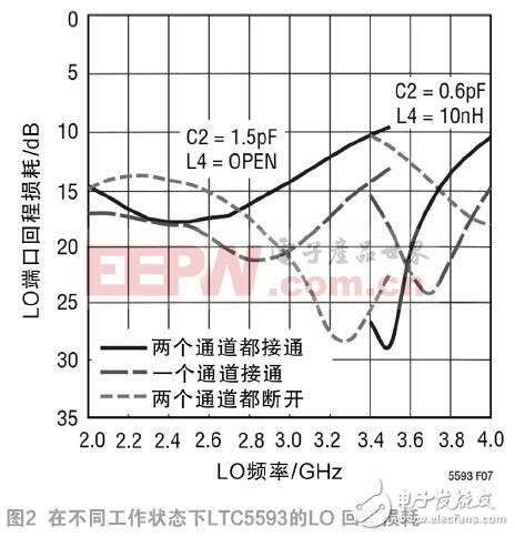
The LO path uses a common balun to convert a single-ended input to a differential LO and then drive a separate buffer amplifier for each channel. This separate LO drive topology maintains the phase coherence of the LO signals to both mixers while providing excellent channel isolation. In addition, to avoid undesired VCO load pull or interference to the VCO, a constant 50Ω LO input impedance match is maintained in all modes of operation, even when one or two mixer stages are turned "on" and "off". Broken time is no exception. 50Ω impedance matching in the frequency range of 2.1GHz to 3.4GHz is achieved by adding a 1.5pF external series capacitor C2. This capacitor is also required for DC isolation. For the higher 3.6 GHz band, adding a 10nH shunt inductor on the power supply side of the capacitor provides good return loss at the LO. Figure 2 shows the LO input return loss of the LTC5593 under various operating conditions. This feature eliminates the need for an external LO buffer stage.
Traditional base stations keep their environment temperature controlled and require components to function properly at temperatures up to +85°. However, smaller cells and remote radio heads are a more demanding environment for components that require proper operation at temperatures up to +105 °C. The LTC5593 mixer is designed for temperatures up to +105 ° C and is tested at this temperature to meet the requirements.
To minimize solution size, the LTC5593 family of mixers is packaged in a small 5mm x 5mm 24-lead QFN package. However, smaller package sizes only play a part in reducing overall solution size. The device's high level of integration reduces the number of external components required to approximately 19, minimizing board space, complexity and cost.
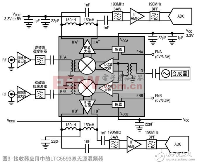
2 receiver applicationThe function diagram of the LTC5593 mixer in the dual channel receiver is shown in Figure 3. The single-ended RF signal is amplified and filtered before being applied to the mixer input. In this example there is a differential IF signal path, so there is no need for an IF balun. The SAW filter, IF amplifier, and lumped component bandpass filters are differential. The receiver in this example supports a 150MHz IF bandwidth when using the circuit component values ​​shown in Figure 3. By reducing the impedance between the differential pins, a larger bandwidth can be achieved, but the gain is slightly reduced.
In many MIMO receivers, highly selective SAW filters are used to isolate unwanted spurious noise and noise at the mixer output. The 8dB conversion gain of the mixer compensates for the high insertion loss of these filters, reducing their effect on the noise floor of the system. The overall performance of the mixer is high, so the receiver can withstand the filter loss while meeting the sensitivity and non-parasitic requirements.

Another important performance goal of multi-channel receivers is channel-to-channel isolation. Channel-to-channel isolation refers to the ratio of the IF output value of the undriven channel to the IF output value of the driven channel. This parameter is usually specified to be 10 dB higher than the antenna to antenna isolation to avoid degrading system performance. Based on a precision IC design, the LTC5593 achieves 44dB channel-to-channel isolation at 3.6GHz and 52dB at 2.6GHz, which meets the needs of many multi-channel applications.
3 power consumption and solution sizeAs multi-band/multi-mode base station topologies mature and the definitions of 4G to future 5G network systems become more precise, wireless infrastructure systems are shifting to new platform configurations that allow for minimal hardware and software. Change to meet a variety of different frequency bands or mode requirements. The LTC559x family of dual mixers all have the same pinout, making it easy to use the same board layout for all bands.

The continued growth of wireless communications has also spurred the use of smaller cells, such as picocells and femtocells. The need for more smaller cells and the increasing use of remote radio heads has imposed additional constraints on infrastructure systems, requiring higher levels of integration and smaller solution sizes.
As the number of cells increases, power consumption becomes more and more important as the cost of energy increases proportionally. On the other hand, in the remote radio head, thermal stress becomes a major problem due to passive cooling. Simply reducing the size of the solution is not enough, as system size reductions can lead to increased power density, increased junction temperature, and reduced potential component reliability. Therefore, it is necessary to reduce system power consumption and size at the same time. This goal is challenging because it must be guaranteed not to affect RF performance.

In the past, integrating two separate mixers onto a single chip resulted in an overall power consumption of 2W. To reduce power consumption, the LTC5593 family of mixers is designed to operate at 3.3V instead of 5V. Low-voltage circuit design methods reduce power consumption without affecting conversion gain, IIP3, or noise figure performance. The only parameter that is affected by the lower supply voltage is the output P1dB performance, which is approximately 10.4 dBm. When driving a 200Ω load impedance, P1dB is limited by the output voltage swing of the open collector of the IF amplifier. For applications requiring higher P1dB, these mixers are specifically designed to allow the use of a 5V supply on the IF amplifier. After the power supply voltage is increased, the P1dB is improved to 13.7 dBm.
As shown in Table 1, the dual mixer achieves excellent performance while power consumption is just over 1.3W when both channels are enabled. To further reduce power, each channel can be independently turned off on demand by using independent enable control. The ISEL pin allows the user to switch to a low current mode to further reduce DC power consumption when acceptable linearity reduction is acceptable.
4 ConclusionTo meet the stringent requirements of emerging 5G multi-channel infrastructure receivers, the LTC5593 dual passive downconverting mixer delivers the high performance required to drive increased frequency and bandwidth. The mixer combines high conversion gain, low noise figure, and high linearity to improve overall system performance while low power consumption and small solution size to meet ever-increasing base stations and remote radio heads. Strict requirements.
1. This product is used to convert the car power supply of mobile phone chargers
2. This product has over-current short-circuit overload protection
3. Insert this product into the cigarette lighter socket of the car
4. Confirm whether the power indicator light of this product is on
5. Insert the mobile phone charger into the socket of this product
6. This product is used in mobile phones, PHS, mobile phone line chargers, travel chargers, universal chargers, etc.
150w Car Inverter, 150W Power Inverter, Car Charger Inverter with USB
Shenzhen Jinziming Electronic Technology Co.,LTD , https://www.powerchargerusb.com
