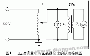
1 Principle of measuring the current transformer ratio by voltage method The method of measuring the current transformer ratio by voltage method is suitable for field test. Its advantages are less equipment, simple circuit and easy operation. The test wiring diagram is shown in Figure 1.

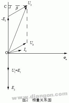
The voltmeter V monitors the secondary voltage of the current transformer under test, and the millivoltmeter mV monitors the primary side voltage of the measured current transformer. This method is similar to the method of measuring the induced potential of the iron core. Its vector diagram is shown in Figure 2.

Secondary applied voltage: U2 = -E 2 + US
Induction potential: E 1 = 4.44fN1F m
E 2 = 4.44fN2F m
The ratio of the ideal current transformer: K = N 2 / N 1 = E 2 / E 1, and the actual measured ratio: K = U2 / U1 = E 2 / U1, as seen from the above equation, the ideal current transformer changes The difference between the ratio and the actual ratio is approximately the result of U2 = E 2 . In fact, as shown in FIG. 2, since the angular difference is small, it can be considered that U 2 and the line segment OC are equal in length. That is, U2 = E 2 + USsinβ, so there is a difference between U2 and E 2: USsinβ = I 0(R + jX)sinβ , because the resistance and leakage reactance of the secondary winding of the current transformer are relatively small, as long as the control When the excitation current I 0 is in a suitable range (mA level), the error caused by the difference between U 2 and E 2 can be neglected. By using the voltage method to measure the current transformer ratio, it can be higher. Precision.
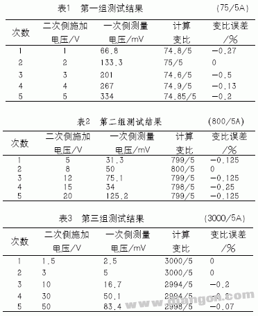
2 Examples and measurement results According to the above theoretical analysis, in order to verify the correctness and accuracy of the method, a ratiometric test was performed on multiple current transformers with different models and different ratios. The following is an excerpt of several sets of test results, the first set of 75/5A supported retracement current transformers, the second set of 800/5 through-wall current transformers, and the third set of 3000/5 busbar type current transformers. The test results of the above three sets of current transformers are recorded in three groups of tables. It can be seen from Table 1, Table 2 and Table 3. It is completely feasible to measure the ratio of the current transformer by voltage method, and it has certain precision. The ratio error is due to the meter reading error. The voltage method measures the current transformer ratio with the following advantages:
It can measure any current transformer of any ratio and has a wide range of applications;
When the control is appropriate, the error is relatively small;
The test equipment used is small, the operation is simple, and it is more suitable for use on the construction site;
The current transformer to be tested does not pose a danger to people and equipment even if it is opened twice.
In summary, measuring the current transformer ratio by voltage method is a simple, practical and effective test method, which is worthy of promotion.

Customers looking to customize electronic products for their business applications, we are here to understand your needs and help you with electronic hardware design. We have engineering resources to assist your business with electronic work. For any level of electronics problem you are facing right now, we have experts who can solve your problem.
PCB Prototype,PCB Prototype Design,PCB Gerber Design,PCBA Program Development,PCB Schematic
Huizhou Liandajin Electronic Co., Ltd , https://www.ldjpcb.com
