
There are many types of LCD interfaces, and the classification is very fine. Mainly look at the LCD drive mode and control method, currently there are several types of color LCD connection on the phone: MCU mode, RGB mode, SPI mode, VSYNC mode, MDDI mode, DSI mode. MCU mode (also written in MPU mode). Only the TFT module has an RGB interface.
However, the application is more MUC mode and RGB mode, the difference is as follows:
1. MCU interface: will decode the command, the timing generator generates timing signals, drive COM and SEG drivers.
RGB interface: When writing LCD register setting, there is no difference between the MCU interface and the MCU interface. The only difference is the way the image is written.
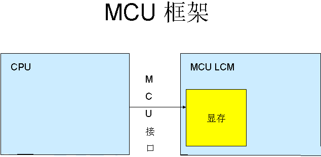
2. In the MCU mode, since the data can be stored in the internal GRAM of the IC and then written to the screen, this mode LCD can be directly connected to the MEMORY bus.
It is different when using RGB mode. It has no internal RAM. HSYNC, VSYNC, ENABLE, CS, RESET, RS can be directly connected to the GPIO port of MEMORY, and the waveform is simulated with GPIO port.
3. MPU interface mode: display data is written to DDRAM, which is often used for still picture display.
RGB interface mode: display data is not written to DDRAM, direct write screen, fast, often used for displaying video or animation.
The main differences between the MCU interface and the RGB interface are:
MCU interface mode: Display data is written to DDRAM, which is often used for still picture display.
RGB interface mode: display data is not written to DDRAM, direct write screen, fast, often used for displaying video or animation.
MCU mode
Because it is mainly used in the field of single-chip microcomputers, it is named after it. It is widely used in low-end and mid-range mobile phones, and its main feature is that it is cheap. The standard terminology of the MCU-LCD interface is Intel's 8080 bus standard, so I80 is used to refer to the MCU-LCD screen in many documents. Mainly can be divided into 8080 mode and 6800 mode, the main difference between the two is timing. Data bit transmission has 8 bits, 9 bits, 16 bits, 18 bits, and 24 bits. The connection is divided into: CS/, RS (register selection), RD/, WR/, and then the data line. The advantage is that the control is simple and convenient, and no clock and synchronization signals are needed. The disadvantage is that it costs GRAM, so it is difficult to achieve a large screen (3.8 or above). For the LCM of the MCU interface, the internal chip is called the LCD driver. The main function is to transform the data/command sent by the host into RGB data of each pixel and display it on the screen. This process does not require point, line, or frame clocks.
The Driver IC of the LCD of the MCU interface is equipped with GRAM. The Driver IC acts as a coprocessor of the MCU and accepts the Command/Data sent by the MCU, which can work relatively independently. For the LCM (LCD Module) of the MCU interface, the internal chip is called the LCD driver. The main function is to transform the data/command sent by the host into RGB data of each pixel and display it on the screen. This process does not require point, line, or frame clocks.
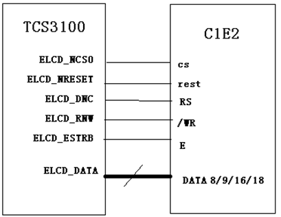
M6800 mode
The M6800 mode supports an optional bus width of 8/9/16/18-bit (default is 8 bits). The actual design idea is the same as the I80. The main difference is that the bus control read/write signals of this mode are combined. One pin (/WR) is added with a latch signal (E) and the data bit is transmitted with 8 bits, 9 bits, 16 bits and 18 bits.
I8080 mode
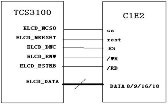
The I80 mode connection is divided into: CS/, RS (register selection), RD/, WR/, and then the data line. The advantage is that the control is simple and convenient, and no clock and synchronization signals are needed. The disadvantage is that it costs GRAM, so it is difficult to achieve a large screen (QVGA or higher).
The standard name of the MCU interface is I80, and there are five control pins for the pin:
CS chip select signal
RS (set 1 to write data, set 0 to write command)
/WR (0 means write data) Data command distinguishes signal
/RD (0 means read data)
RESET reset LCD (reset with fixed command series 0 1 0)
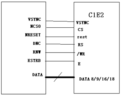
VSYNC mode
This mode is actually adding a VSYNC signal to the MCU mode, which is applied to the motion picture update, which is very different from the above two interfaces. This mode supports direct animation display, which provides a minimal change to the MCU interface and an animation display solution. In this mode, the internal display operation is synchronized with the external VSYNC signal. Animated display at a higher rate than internal operations can be achieved. However, due to the different modes of operation, this mode has a limitation on the rate, that is, the write rate to the internal SRAM must be greater than the rate at which the internal SRAM is read.
RGB mode
The large screen adopts more modes, and the data bit transmission also has 6 bits, 16 bits and 18 bits, and 24 bits. Connections generally include: VSYNC, HSYNC, DOTCLK, CS, RESET, and some also require RS, and the rest is the data line. Its advantages and disadvantages are exactly the opposite of the MCU mode.
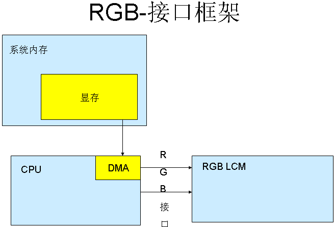
The main difference between the MCU-LCD screen and the RGB-LCD screen is the location of the memory. RGB-LCD memory is played by system memory, so its size is only limited by the size of the system memory, so RGB-LCD can make larger sizes, like 4.3" now only entry level, and 7 in MID" The 10" screens are all used in large quantities. The design of the MCU-LCD is as long as the memory of the microcontroller is small, so the memory is built into the LCD module. Then the software updates the memory by special display commands, so the MCU screen It can't be done very much. At the same time, the display update speed is slower than RGB-LCD. The display data transmission mode is also different. The RGB screen only needs to store and organize the data. After the display is started, the LCD-DMA will automatically pass the data in the memory to RGB. The interface is sent to the LCM, and the MCU screen needs to send a command to draw the MCU's internal RAM (that is, it cannot directly write the RAM of the MCU screen). Therefore, the RGB display speed is obviously faster than the MCU, and the MCU-LCD is also used for playing video. slower.
For the LCM of the RGB interface, the output of the host is directly the RGB data of each pixel, and no conversion is required (except GAMMA correction, etc.). For this interface, an LCD controller is required in the host part to generate RGB data and Point, line, and frame sync signals.
Color TFT LCD screens mainly have two kinds of interfaces: TTL interface (RGB color interface), LVDS interface (package RGB color into differential signal transmission). The TTL interface is mainly used for small-size TFT screens of 12.1 inches. The LVDS interface is mainly used for large-size TFT screens of 8 inches or more. There are many TTL interface lines and short transmission distances; the LVDS interface has a long transmission distance and a small number of lines. The large screen uses more modes, the control pins are VSYNC, HSYNC, VDEN, VCLK, S3C2440 supports up to 24 data pins, and the data pin is VD[23-0].
The image data sent by the CPU or graphics card is a TTL signal (0-5V, 0-3.3V, 0-2.5V, or 0-1.8V), and the LCD itself receives the TTL signal, because the TTL signal is transmitted at a high rate over a long distance. Poor performance, poor anti-interference ability, and later proposed a variety of transmission modes, such as LVDS, TDMS, GVIF, P&D, DVI and DFP. They actually only encode the TTL signal from the CPU or graphics card into various signals for transmission, and decode the received signal on the LCD side to get the TTL signal.
But regardless of the transmission mode, the essential TTL signal is the same.
Note: TTL/LVDS are the transmission modes of two kinds of signals respectively. TTL is high level means 1 and low level means 0 mode. LVDS is positive and negative two corresponding waveforms. The difference between two waveforms is used to indicate that it is currently 1 or 0
SPI mode
It is used less, there are 3 lines and 4 lines, the connection is CS/, SLK, SDI, SDO four lines, the connection is small but the software control is more complicated.
MDDI mode (MobileDisplayDigitalInterface)
Qualcomm's interface MDDI, proposed in 2004, improves mobile phone reliability and reduces power consumption by reducing connectivity, which will replace SPI mode and become a high-speed serial interface for mobile. The connection is mainly host_data, host_strobe, client_data, client_strobe, power, GND several lines.
DSI mode
This mode serial bidirectional high-speed command transmission mode, the connection has D0P, D0N, D1P, D1N, CLKP, CLKN.
Cat 6 Lan Cable,Cat6 Ethernet Cable,Outdoor Cat6 Cable,Lan Cable Cat6
Zhejiang Wanma Tianyi Communication Wire & Cable Co., Ltd. , https://www.zjwmty.com