
For the programming of AMetal framework and interface (on), the AMetal framework is introduced in detail. By reading this book, you can learn the highly multiplexed software design principles and development ideas for interface programming, focusing on your own core domain. ", change your own programming thinking, and achieve common progress between the company and the individual." Authorized by Professor Zhou Ligong, from now on, the Zhiyuan Electronic Public Number will serialize the contents of the book, and is willing to share it.
The fourth chapter is interface-oriented programming , this article includes: 4.3 LED digital tube.
4.3 LED digital tube
> > > 4.3.1 Static display
As shown in Figure 4.10, there is an LED digital tube circuit composed of two common anode LN3161BS. R1 to R8 are current limiting resistors, and c1 and c2 are connected in parallel internally. If the segment selection terminals a to dp and the bit selection terminals com0 and com1 are connected to the PIO0_8~PIO0_15 and PIO0_17 and PIO0_23 of the AM824-Core, the pen segment can be controlled by the program. Since all eight segments of the digital tube must be powered by the com port, it is necessary to increase the triode to increase the drive current of the com port to compensate for the lack of LPC824 GPIO drive current. When com is low, the triode is turned on, and c1 and c2 of the digital tube are high level, that is, the digital tube is strobed. At this time, as long as the selected end of any segment of the digital tube is low, the corresponding pen segment of the digital tube is illuminated.
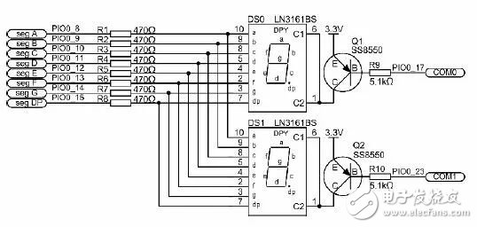
Figure 4.10 LED display circuit diagram
The MiniPort-View digital tube module is connected to the AM824-core through the MiniPort B, and the other unused I/Os are taken out through the MiniPort A (pin header) to implement horizontal stacking of the modules, which corresponds to the MiniPort of the AM824-Core. The function definition of interface J4 is shown in Figure 4.11.
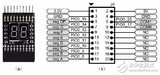
Figure 4.11 Digital Tube Module Physical and Interface Definition
The “Day†digital display can display the hexadecimal letters AbCdEF or some other very simple symbols in addition to the decimal numbers 0-9. According to the binary calculation method, there are 256 combinations in the 8-segment display, and the display of the "dot (dp)" is removed. The combination of the pen segments is 128 ( 2 7 ), and the numbers 0 to 9 have only 10 symbols, so to get The display we want must encode the display segment. Obviously, if you want to light a pen segment of the digital tube, you only need to set the corresponding pen segment to 0. That is, output low level to com0 terminal, and output low level to b and c segments, and light the LED to get the character "1". It can be seen that, according to the arrangement of the numbers of strokes, it is easy to obtain 10 numbers 0 to 9 total 10 display characters, and the 7-segment digital digital tube 10 number field code table is shown in Table 4.2.
Table 4.2 Seven-segment common anode digital pipe segment code table
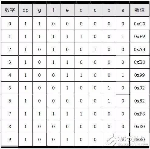
If the segment code is represented by an 8-bit value, when the corresponding bit is 0, it means that the corresponding segment is lit. Bits 7~0 correspond to dp~a respectively. If bit0 is 0, it will light a. For easy access, you can store the segment code in an array. which is:

The AMetal software package provides board-level initialization functions, segment code transfer functions, bit code transfer functions, and digital display scan functions that extinguish all digital tubes. The function interface is detailed in Listing 4.10.
Listing 4.10 digitron0.h interface
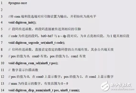
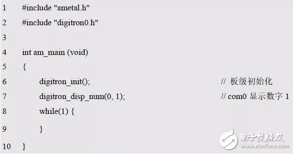
Where code is the segment code corresponding to the number 0~9 to be displayed, pos is the number subscript (0~1) corresponding to com0 or com1, and num is the number 0~9 to be displayed. When these functions are called later, only "#include "digitron0.h"" is required. For example, the number 1 is displayed on the com0 digital tube, as shown in Listing 4.11.
Listing 4.11 Static Display Number 1 Sample Program
If a single digital tube is cycled to display 0~9, and the cycle time is 1s, obviously the display time is also 1s, then this is a simple second counter, as shown in Listing 4.12.
Program Listing 4.12 Second Counter Sample Program
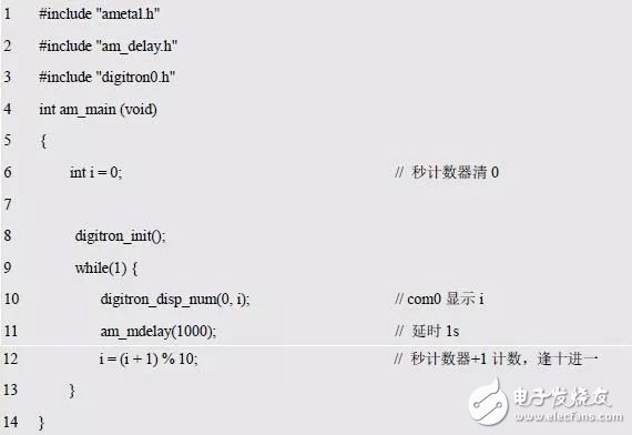
When you see the "i = (i + 1) % 10;" code in Listing 4.12(9), is there a feeling of deja vu? This line of code was extracted from the LED street light experiment. If you need a countdown? Then modify it to "i= ((i - 1) + 10) % 10;". What if you want to count down from 9? Then change the initial value of i to 9. At this point, the loop display of 0~9 has been realized. Can it display 0~99 cyclically? This is the digital tube dynamic scan display that will be introduced below.
> > > 4.3.2 Dynamic display
If you want to display multiple digits, you need to connect multiple digital tubes together. At this point, there will be a large number of segment selection problems. For example, two digital tubes require 2×8=16 segment selection signals, while the LPC824 has only 16 I/Os, which cannot meet the demand, and the more pins are used. The connection will become more complicated. Therefore, in order to avoid waste of resources and complicated wiring by avoiding the use of too many pins, a dynamic scanning method has been invented to realize display of a plurality of digital tubes.
Since the segment codes of the digital tube are connected together, the segment codes of the two digital tubes must be the same at the same time. If the two common terminals (com) are both effective to realize the display of the two digital tubes, then It will inevitably show the same content. How to do? Time-division display, that is, the digital tube 0 is displayed normally for a period of time (com0 is valid, com1 is invalid, the segment code is the graphic that needs to be displayed by the digital tube 0), and the digital tube 1 is displayed normally for another period of time (com1 is valid, com0 is invalid, and the segment code is digital) Tube 1 needs to display the graph). To display a value of 12? That is, 1 is displayed at com0 and 2 is displayed at com1, as shown in Listing 4.13.
Listing 4.13 shows the value 12 sample program
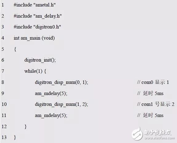
Although the numbers are displayed in turn during the actual operation, as long as the speed of the rotation operation reaches a certain range, the human eye can be seen to have the same effect as the overall display, just like the movie technology we often watch.
If you look closely at the experimental phenomenon, you can see that although the number displayed is 12, the 1 and 2 of the digital tube display will have another number of shadows. Com0 shows 1 but can also see the shadow of 2.
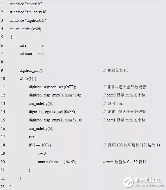
Digitron_disp_num() is a simple combination of digitron_com_sel() and digitron_segcode_set(). The display process is to transmit the bit code first and then the segment code, so that a time gap is generated between the transmission bit code and the transmission segment code. When the new com end is valid, the previous segment code is still being used, so there is a short-lived error. How to do? All digital tubes can be extinguished during this time to avoid false displays. which is:

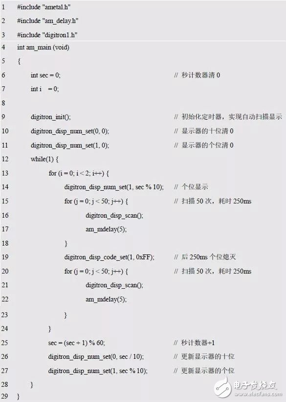
How do you cycle through 0 to 59? The value to be displayed is incremented by one, as detailed in Listing 4.14.
Listing 4.14 0~59 second counter example program (1)
Can the program continue to optimize? The problem now is that in order to display a data, even if the data has not changed, the digital tube must be dynamically scanned, otherwise it cannot be displayed. First, the data to be displayed is stored in a buffer (storage unit), and then the data to be displayed is read from the buffer at intervals. which is:

The function to read the buffer data to achieve dynamic scanning is detailed in Listing 4.15.
Listing 4.15 Dynamic Scan Display Function
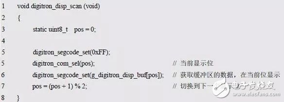
It can be seen that the segment code of the buffer is the data to be displayed currently. When it is switched again, the function is continued to be called, the data is displayed in the next bit, and so on. Since the bit variable pos is changed each time based on the last displayed bit, it must be declared as a static variable. Obviously, dynamic scanning can be realized by storing the displayed content in a buffer and ensuring that the function is called at a certain time interval (delay after display of each digital tube).
In order to facilitate the multiplexing of the digital tube program, the above code is all stored in the digitron1.c file, and the function declaration is placed in the digitron1.h file. Its interface is as follows:
(1) digitron_init(): Initialize the relevant pin;
(2) digitron_disp_scan(): dynamic scan function.
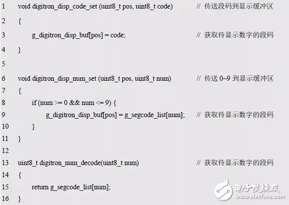
Since the content to be displayed is stored in the buffer, and the segment code table may also be accessed, the caller is not allowed to directly manipulate the variables, arrays, etc., and based on this, three interface functions are added, which are respectively transmitting the segment code to the display buffer. Area, transfer the number 0~9 to the display buffer and get the segment code of the number to be displayed. The corresponding code is shown in Listing 4.16.
Listing 4.16 Operation Buffer and Segment Table Interface Functions
If you want to display "3." on com0, you can use it like this:

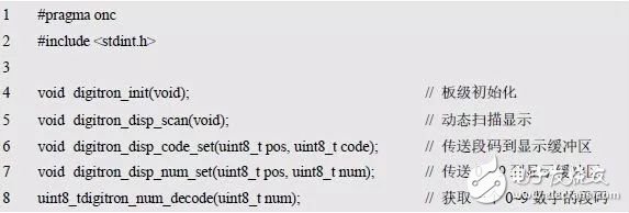
Finally, all of these interfaces are declared in the digitron1.h file shown in Listing 4.17. For the relevant implementation code, see the digitron1.c file introduced in "Introduction to Atomal - Dynamic Display".
Listing 4.17 digitron1.h file contents
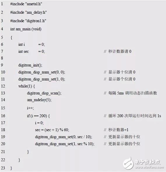
Note that in the digitron1.h interface, digitron_disp_num_set() and digitron_disp_code_set() have been used instead of digitron_disp_num() and digitron_disp_code(), and Listing 4.18 shows the 0~59 second counter sample program through an iterative loop.
Listing 4.18 0~59 second counter sample program (2)
> > > 4.3.3 Blinking processing
During the display process, sometimes in order to modify the value of a digital tube, the digital tube needs to be flashed. In the temperature collection occasion, when the temperature exceeds a certain value, the displayed temperature value can be fully flashed to attract the attention of the observer.
In fact, as long as the digital tube is displayed for a period of time and extinguished for a period of time, a flickering effect is produced. Obviously, it is sufficient to operate the buffer directly. Assume that it flashes 2 times per second and blinks continuously in the unit. See Listing 4.19 for details.
Listing 4.19 implements the second counter flashing (1)
In the program, 1s flashes 2 times, each flashing takes 500ms, that is, 250ms is displayed, and 250ms is extinguished. After the end of each second, the second counter is incremented by one. Obviously, the tenth bit of the second counter can be flashed by the same method. It can be seen that the flicker only needs to alternately transmit the segment code displayed normally and the segment code to be extinguished. Since the segment code displayed by the extinction is very special, it is fixed at 0xFF. Therefore, the segment transfer function digitron_segcode_set() is called in the digitron_disp_scan() function as long as the corresponding segment code is transmitted at the appropriate time. By modifying the function, it can transmit the segment code normally displayed in the buffer for a period of time, and the segmentation code 0xFF displayed after being turned off for a period of time can also achieve flickering. See Listing 4.20 for details.
Listing 4.20 The digitron_disp_scan() function with blinking function (1)
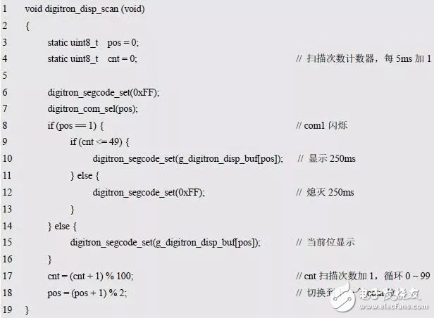
The program divides the time into 500ms time slices. When it needs to flash, it displays 250ms, extinguishes 250ms, calls digitron_disp_scan() every 5ms, cnt loop counts +1. How to make the seconds counter flash in ten places? Modify if(pos == 1) directly to if(pos == 0).
Obviously, the blinking state and display state of the digital tube can be represented by a flag bit, that is, 0 means display, 1 means flashing, and bit0 and bit1 indicate the states of com0 and com1, respectively. Define a global variable as follows:

If bit1 flashes, the initial value of bit1 is set to 1. which is:

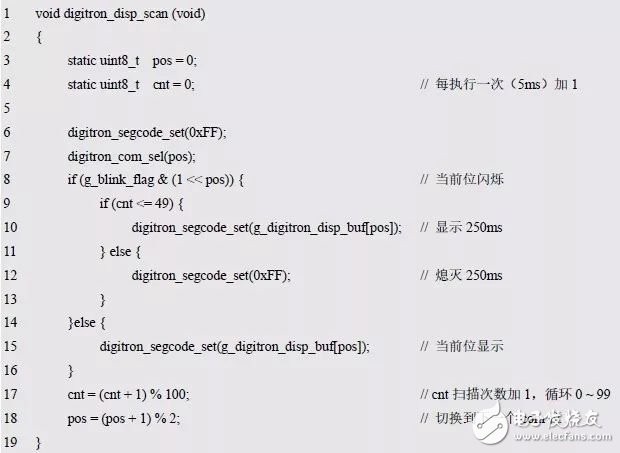
In this way, you need to get the bits that need to be flashed according to the value of the variable, as shown in Listing 4.21. Obviously, the flicker can be achieved by setting the corresponding position of g_blink_flag to 1, otherwise the corresponding bit is cleared to 0.
Listing 4.21 The digitron_disp_scan() function with blinking function (2)
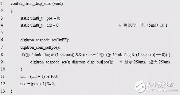
To improve the readability of the program, further optimize the two if-else statements, as shown in Listing 4.22.
Listing 4.22 The digitron_disp_scan() function with blinking function (3)
Since the g_blink_flag variable is defined in the implementation code, it cannot be directly supplied to the user for modification. Therefore, an interface function must be provided to set the blinking bit. The corresponding code is shown in Listing 4.23.
Listing 4.23 digitron_disp_blink_set() function
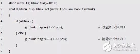
The pos of digitron_disp_blink_set() is used to specify the location of the nixie that sets the flicker property, isblink sets the flicker property, the value is AM_TRUE for flashing, and AM_FALSE for flashing. Am_bool_t is a type that AMetal customizes in the am_types.h file. The value of this type of data can only be AM_TRUE (true) or AM_FALSE (false). The method for setting com0 to flash is as follows:

Set com0 to stop flashing as follows:

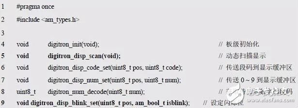
Add the interface function of digitron_disp_blink_set(), see digitron1.h as shown in Listing 4.24.
Listing 4.24 digitron1.h file contents
With this interface function, it is easy to achieve flicker, and Listing 4.25 implements the second counter flashing.
Listing 4.25 implements the second counter flashing (2)
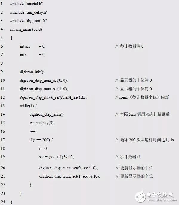
It can be seen that compared with the program list 4.18, the flicker function is realized by adding only one line of code. Obviously, the design of the interface is very important.
Iwatch Screen Protector,Tempered Glass Package,40Mm Tempered Glass,44Mm Tempered Glass
Shenzhen TUOLI Electronic Technology Co., Ltd. , https://www.hydrogelprotector.com