The auxiliary relay is the most abundant type of relay in the plc. The general auxiliary relay is similar to the intermediate relay in the relay control system.
The auxiliary relay cannot directly drive an external load, and the load can only be driven by the external contacts of the output relay. The normally open and normally closed contacts of the auxiliary relay can be used indefinitely when programmed in the PLC.
The auxiliary relay is composed of M and decimal numbers (only the input and output relays use octal numbers).
1. General auxiliary relay (M0~M499)
The FX2N series has a total of 500 general-purpose auxiliary relays. When the general auxiliary relay is running in the PLC, if the power supply is suddenly turned off, all the coils are turned OFF. When the power is turned on again, the remaining ones remain OFF except for being turned ON by an external input signal, and they have no power-off protection function. General-purpose auxiliary relays are often used as auxiliary operations, state temporary storage, shifting, etc. in logic operations.
According to the need, the M0 to M499 can be changed to the power-off holding auxiliary relay by program setting.
2. Power-off holding auxiliary relay (M500~M3071)
The FX2N series has 2,572 power-off auxiliary relays from M500 to M3071. Unlike conventional auxiliary relays, it has a power-off protection function that remembers the state of the power interruption transient and reproduces its state after power-on. It maintains its original state when the power is turned off because the lithium battery in the PLC holds the contents of their image registers when the power is interrupted. Among them, M500~M1023 can be set as general auxiliary relay by software.
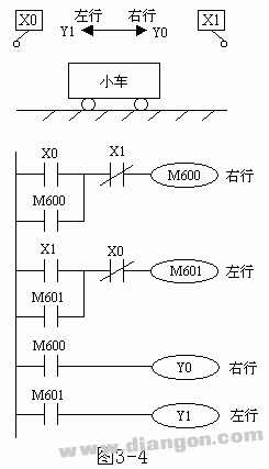
The following uses the reciprocating motion control of the car to illustrate the application of the power-off holding auxiliary relay, as shown in Figure 1.

Figure 1 The role of the power-off retention auxiliary relay
In the forward and reverse movement of the car, the M600 and M601 control output relays drive the car movement. X1 and X0 are limit input signals. The running process is X0=ON→M600=ON→Y0=ON→car right line→blackout→car stop midway→power on (M600=ON→Y0=ON) then right line→X1=ON→M600=OFF, M601 =ON→Y1=ON (left line). It can be seen that since the M600 and M601 have power-off retention, after the power failure is stopped in the middle of the car, once the power is restored, the M600 or M601 still remembers the original state, and they will control the corresponding output relays, and the car will continue to move in the original direction. If the auxiliary relay is not powered off, the car will not move again when the car is cut off in the middle.
3. Special auxiliary relay
There are a large number of special auxiliary relays in the PLC, each with their own special functions. There are 256 special auxiliary relays in the FX2N series, which can be divided into two types: contact type and coil type.
(1) Contact type The coil is automatically driven by the PLC, and the user can only use its contacts. E.g:
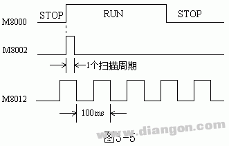
M8000: Run monitor (turned on during PLC operation), M8001 is opposite logic to M8000.
M8002: Initial pulse (only momentarily turned on at the beginning of the run), M8003 is opposite logic to M8002.
M8011, M8012, M8013, and M8014 are special auxiliary relays that generate clock pulses of 10ms, 100ms, 1s, and 1min, respectively.
The waveform diagrams of M8000, M8002, and M8012 are shown in Figure 2.

Figure 2 M8000, M8002, M8012 waveform diagram
(2) Coil type The PLC performs a specific action after the coil is driven by the user program. E.g:
M8033: If the coil is energized, the output image memory and data register contents are maintained when the PLC is stopped.
M8034: If the coil is energized, the output of the PLC is completely disabled.
M8039: If the coil is energized, the PLC will work according to the scan time specified in D8039.
Fourth, the state device (S)
The state machine is used to record the status of the system in operation. It is an important programming component for programming a sequence control program. It is used in conjunction with the step sequence command STL described later.
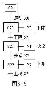
As shown in Figure 3-6, we briefly introduce the role of the stater S with the robot action. When the start signal X0 is valid, the robot is lowered, and the workpiece is clamped to the lower limit X1. When the tightening in-position signal X2 is ON, the robot is stopped when it reaches the upper limit X3. The whole process can be divided into three steps, each step is recorded with a state machine S20, S21, S22. Each state device has its own set and reset signals (such as S21 set by X1 and X2 reset) and has its own operations (drive Y0, Y1, Y2). From the start of the start, the state of the next state action automatically returns to the original state as the state action shifts from top to bottom. In this way, the work of each step does not interfere with each other, and it is not necessary to consider the interlocking of components between the unsynchronized ones, so that the design is clear and concise.

Figure 3 The role of the state machine (S)
There are five types of state machines: initial state device S0 ~ S9 a total of 10 points; zero return state device S10 ~ S19 a total of 10 points; general state machine S20 ~ S499 a total of 480 points; with state power off state controller S500 ~ S899 A total of 400 points; state machine for alarm (can be used as external fault diagnosis output) S900 ~ S999 a total of 100 points.
Note when using the state machine:
1) The state machine has the same number of normally open and normally closed contacts as the auxiliary relay;
2) When the state device is not used with the step sequence command STL, it can be used as the auxiliary relay M;
3) The FX2N series PLC can set S0 to S499 to the state device with power-off hold function by program setting.
We provide quick-turn injection molding by many types of materials, like ABS, PA66, PBT, TPU, TPE, PVC, PE, NYLON 6, PC, silicone, TPE, EPDM, PUR, etc. Special for some plastic parts. Our advantages in internal prototyping, bridge tooling and short-run manufacturing, which can eliminate the costly and time-consuming for customers a lot.
ETOP experienced to support one-stop cable assembly solution service, including wire harness, palstic enclosure, silicone, metal, PCBA, etc.
Injection Molding Parts,Plastic Injection Molding,Low Cost Plastic Injection Molding,Plastic Mold Injection Molding
ETOP WIREHARNESS LIMITED , https://www.wireharnessetop.com
