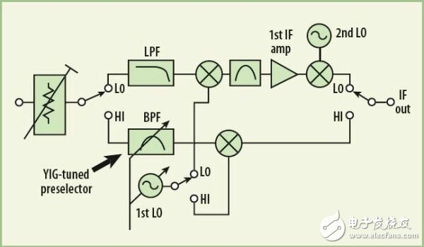
In recent years, modern spectrum analyzers have made significant improvements in low-frequency analog accuracy and digital signal processing (DSP) devices, especially front-end intermediate frequency (IF) filters. Although the spectrum analyzer has high accuracy at the RF frequency, the accuracy at the microwave frequency is not generally improved. Due to the high requirements of modern spectrum analyzers for some applications, including signal analysis using advanced wideband digital modulation formats, it is difficult to achieve higher accuracy even with the best spectrum analyzer design. Fortunately, Agilent Technologies' latest MXA signal analyzer platform integrates sophisticated hardware design and clever measurement algorithms to help users maintain optimal accuracy without the need for special input signals or external test signals.
The Microwave Spectrum Analyzer uses a tunable preselection filter to improve performance by removing unwanted mixer images and harmonic response from the local oscillator (LO). Unfortunately, these preselectors are unstable and must be tuned frequently, and proper preselector tuning typically requires that the signal at the frequency of interest be approximated as a CW statistical distribution. In the new MXA signal analyzer, a complete noise source is used as the tuning signal for the preselected filter, which helps ensure that filter accuracy is an integral part of the automated routines in the instrument.
Modern spectrum analyzers operating at 26.5 GHz have a "low frequency band" and a "high frequency band" channel, as shown in Figure 1. The low frequency band typically operates at 3 GHz or higher. In the low frequency band, the signal is upconverted to a high IF band close to 4 GHz or higher and then downconverted to a lower IF band close to 300 MHz. This dual conversion approach can greatly reduce the mixer image response.

The “high-band†frequency range cannot actually be created by the same block diagram as the low-band range, since the primary IF amplifier will have to operate at a frequency at which the amplifier noise and distortion are always unsatisfactory. Operator's request. The alternative module shown in Figure 1 takes a single conversion step to the IF output. In this block diagram, the image response in the primary mixer is only separated by a frequency of twice the IF size (or approximately 600 MHz). These images are not popular in spectrum analyzers. Therefore, a tunable preselection filter (bandpass filter) can be used to remove the image.
To achieve the required rejection and tuning bandwidth at microwave frequencies, the preselection filter is based on yttrium iron garnet (YIG) technology. The behavior of the YIG sphere is controlled in a precise magnetic field that produces a filter passband resonance that removes unwanted images and responses from the spectrum analyzer channel. YIG preselectors typically have a passband bandwidth of approximately 40 to 80 MHz and can be tuned over a wide range of microwave frequencies. When used for frequencies up to 26.5 GHz, a very high resonator quality factor (Q) is required, resulting in excessive cutoff frequencies and also amplitude and frequency instability. Post-tuning drift is a manifestation of the unstable nature of the YIG-tuned bandpass filter. The magnet used to tune the resonant frequency of the YIG ball heats or cools as the selected frequency changes. The temperature change of the magnet affects the size of the magnet and the strength of the magnetic field, which affects the frequency of filter tuning. The mechanical aging process of the magnet/ball structure is similar, which also leads to an increase in instability. Similarly, the relationship between the tuning current and the filter center frequency cannot be accurately modeled by any simple algebraic function. Therefore, even if the tuning is very stable, there is a tuning error. The result is that the frequency tuning error causes an amplitude error (Figure 2).

Figure 2a shows a typical YIG filter response. The x-axis represents the frequency, but since the frequency of the YIG filter is almost proportional to the tuning current, the x-axis can also be considered as the tuning current of the YIG filter. In this example, the smaller tuning current error is mapped to an amplitude error at the operating point that is proportional to the passband slope. The design operating point is the midpoint between the -4dB response points because the design is very robust in terms of tuning error. The YIG filter can be adjusted by measuring with a modern spectrum analyzer. The user can directly adjust the operating current or perform a "preselector center" operation. Since the amplitude response of the spectrum analyzer is factory calibrated under the condition that the preselector is tuned, the best operation is taken. Please note that poor tuning accuracy of the preselector will result in reduced amplitude accuracy.
Figure 2b shows the importance of the YIG filter fetch operation. Point A represents the coordinate position used to factory calibrate the YIG filter frequency response. This point is located on the response curve of the new analyzer at room temperature. Its horizontal position is at the midpoint between the -4dB (relative peak) response frequencies. Point B lies on a congruent curve, and when the ambient temperature changes, the vertical displacement represents the desired total system response change. In addition to changes in ambient temperature, the effects of drift and aging after tuning may result in a point F on the curve. In this case, the amplitude error can be very large. This error can be expressed as length E, which is the difference between response points B and F.
Insulated Power Cable,Bimetallic Crimp Lugs Cable,Pvc Copper Cable,Cable With Copper Tube Terminal
Taixing Longyi Terminals Co.,Ltd. , https://www.lycopperlugs.com
