
The system adopts single-chip microcomputer as the controller, and uses the thermal release human body infrared sensor and the light intensity sensing system to detect the presence or absence of indoors and indoor light intensity. A schematic block diagram of an intelligent lighting control system is proposed, and intelligent lighting is designed on this basis. Part of the hardware circuit of the control system. The system adopts a modular structure design, which is clear and easy to improve and expand. At the same time, it has the advantages of small size, convenient control and high reliability, which can meet the requirements of intelligent lighting control in office places to achieve energy saving purposes.
The indoor ambient light collection circuit indoor ambient light collection circuit is shown in Figure 2. The working principle is that when the indoor natural light intensity of the office is higher than a certain level (ie, setting parameters), the phototransistor D5 exhibits a low resistance state, that is, less than 1 kΩ, and the base voltage of the transistor Q1 will increase, so that the triode Q1 is saturated. Passing, will make the collector of the transistor Q1 output low level, and will not participate in its work. When the indoor natural light intensity of the office is less than a certain level (ie, setting parameters), the phototransistor D5 exhibits a high resistance state greater than 100 kΩ, causing the transistor Q1 to be turned off, and the collector of Q1 outputs a high level to participate in its circuit operation. The variable resistor R24 ​​is a device for adjusting the sensitivity parameter of indoor ambient light illumination, and the magnitude of the resistance will be the conduction of the transistor Q1 under different indoor ambient light intensity parameters, and the circuit composed of R3 and C1 is Designed to prevent external interference, it has the function of preventing interference. 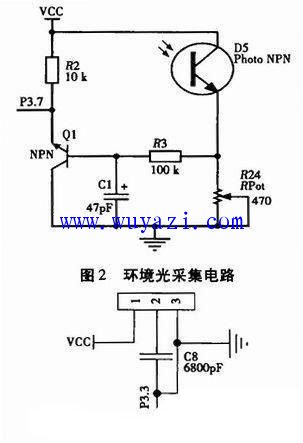
When the human body signal acquisition circuit detects whether the human body is in the office space, the pyroelectric infrared sensor that detects whether the human body exists or not has the functions of high sensitivity, good stability, strong anti-interference, and good delay, and should be selected according to the office. Depending on the working hours of the site and other factors, the pyroelectric infrared sensor of the HT-208 model is usually selected. The human body signal acquisition circuit designed according to the functional characteristics of the chip is shown in Fig. 3. The Pyroelectric Infrared Sensor has an external power supply signal on the No. 1 pin and an external acquisition signal on the No. 2 pin. It is often connected to a capacitor with a capacitance of 6800pF and a pin on the No. 3 pin. The foot is externally grounded, so the pyroelectric infrared sensor is connected to the P3.3 pin end of the AT89S52 of the single-chip microcomputer with the No. 2 pin, and the stability of the pyroelectric infrared sensor is detected to enhance the stability of signal acquisition. Reliable, often a 100 kΩ pull-up resistor is connected to the pin port of the microcontroller.
The watchdog circuit has the functions of watchdog timer, auto reset and voltage threshold monitoring in this circuit. When the system is powered on, power down and the supply voltage is insufficient, the logic state of the microcontroller and bus is uncertain, which will make the MAX705 The RESET pin of the chip outputs a reset signal to the microcontroller to maintain the microcontroller in a reset state to avoid control errors. The circuit is shown in Figure 4. To make the reset more reliable, a 10 kΩ pull-up resistor is connected to the reset output and connected to the reset terminal of the AT89C52. Therefore, when the voltage at the VCC terminal is lower than the reset voltage, the system remains in the reset state. In order to detect the power supply voltage, the power supply Vin is connected to the PFI pin terminal. When the voltage at the PFI terminal is lower than 1.24 V, the PFO terminal outputs an alarm signal, and the WDI terminal is controlled by an internal timer. When WDI is low, Providing protection for the system can prevent the system from working properly due to crashes, program runaways, deadlocks, etc. 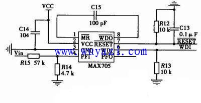
The system is based on the AT89S52 single-chip microcomputer as the main control core, with the ambient light intensity signal and the human body existence as the main input parameters. Through the drive of the relevant circuit, the intelligent control of the office lighting fluorescent lamp is realized. It is more manual management than the traditional human type. The lighting of the office space is more reasonable and more effective to improve the utilization of natural light in the office space, avoiding the waste of electric energy; at the same time, the system has added time control parameters to make the lighting control in the office more in line with the working schedule.
Disposable Vape Bar Pen,Disposable Vape Bar Pen E-Cigarette,Puff Bar Plus E Cigarette,Puff Bar Xtra E Cigarette
KENNEDE ELECTRONICS MFG CO.,LTD. , https://www.axavape.com