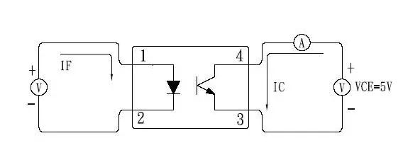
CTR: The minimum value of the current ratio of the arc tube to the phototransistor.
Isolation voltage: The minimum value of the isolation voltage of the light-emitting tube and the phototransistor.
The technical parameters of the optocoupler mainly include LED forward voltage drop VF, forward current IF, current transfer ratio CTR, insulation resistance between input stage and output stage, and collector-emitter reverse breakdown voltage V(BR). CEO, collector-emitter saturation voltage drop VCE(sat). In addition, parameters such as rise time, fall time, delay time, and storage time need to be considered when transmitting digital signals.
Collector-emitter voltage: the minimum value of the withstand voltage between the collector and the emitter When is the optocoupler turned on? When is the cutoff? The CTR-IF characteristic curve of the ordinary optocoupler is non-linear, when the IF is small The nonlinear distortion is especially severe, so it is not suitable for transmitting analog signals. The CTR-IF characteristic curve of the linear optical coupler has good linearity, especially when transmitting small signals, its AC current transmission ratio (ΔCTR=ΔIC/ΔIF) is very close to the DC current transmission ratio CTR value. Therefore, it is suitable for transmitting analog voltage or current signals, enabling a linear relationship between output and input. This is an important feature.
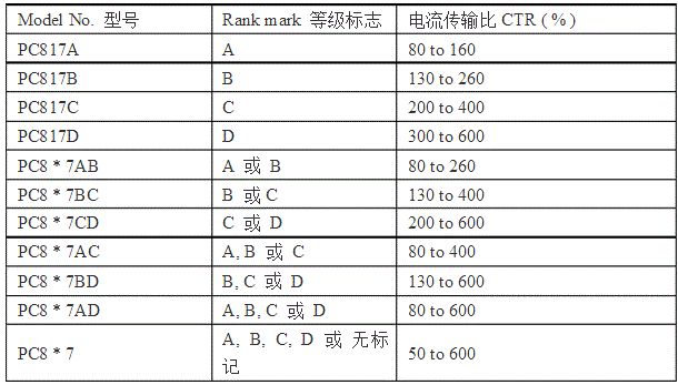
The current transfer ratio is an important parameter of the optocoupler and is usually expressed by the DC current transfer ratio. When the output voltage remains constant, it is equal to the percentage of the DC output current IC to the DC input current IF. Photocouplers using a phototransistor, CTR range is mostly 20% to 300% (such as 4N35), while pc817 is 80% to 160%, Taiwan billion light (such as EL817) can reach 50% to 600%. This indicates that the same output current is required, which requires a smaller input current. Therefore, the CTR parameters have some similarities to the hFE of the transistor.
The use of optocouplers is mainly to provide isolation between the input circuit and the output circuit. When designing the circuit, the following selected optocoupler devices must meet the national and international standards for isolation breakdown voltage; generated by Taiwan Everlight The EL817 series (such as EL817B-F, EL817C-F) optocouplers are currently widely used in China. In view of the switching characteristics of such optocouplers, the linearity is poor, and it is suitable for transmitting digital signals (high and low levels), which can be used for output isolation of the single chip microcomputer; the selected optocoupler device must have a high coupling coefficient.

In the isolation of the switching power supply, and the design of the optocoupler feedback switching power supply, the type and parameters of the linear optical coupler must be correctly selected. In addition to the selection principle of the common optocoupler, the following principles must be followed:
1. It is recommended to use a linear optocoupler, which is characterized by a linear adjustment of the CTR value within a certain range.
2. The allowable range of the current transfer ratio (CTR) of the optocoupler is 50% to 200%. This is because when CTR<50%, the LED in the optocoupler needs a large operating current (IF>5.0mA) to properly control the duty cycle of the monolithic switching power supply IC, which will increase the work of the optocoupler. Consumption. If CTR>200%, when the circuit is started or when the load is abrupt, it is possible to falsely trigger the single-chip switching power supply, which affects the normal output.
3. If an amplifier circuit is used to drive the optocoupler, it must be carefully designed to compensate for the temperature instability and drift of the coupler.
The following are some of the parameters of the common optocoupler PC817 series (for reference only):

