In recent years, the continuous development of device technology based on wide band gap materials and the practical engineering application of silicon carbide devices have received more and more attention. Compared with traditional silicon-based devices, silicon carbide MOSFETs have a smaller on-resistance and fast switching speed. Compared with silicon IGBTs, the conduction loss and switching loss are significantly reduced. The use of SiC MOSFET devices has brought hope to the further improvement of actual system efficiency and the further reduction of system volume. Especially in applications where high efficiency and volume are required, such as photovoltaic inverters and battery charging, the engineering use of SiC MOSFETs has become a hot topic.
At present, the research on the advantages of SiC MOSFET and the reliability of this new material device has been quite extensive. However, as an important part of controlling the turn-on and turn-off of switching power devices, drive design has also become a key link to make full use of the advantages of SiC MOSFET characteristics.
Because SiC products are different from traditional silicon IGBTs or MOSFETs in parameter characteristics, and they usually work in high-frequency application environments, to select the appropriate gate drive chip for SiC MOSFETs, the following aspects need to be considered:
1. Requirements for drive level and drive current
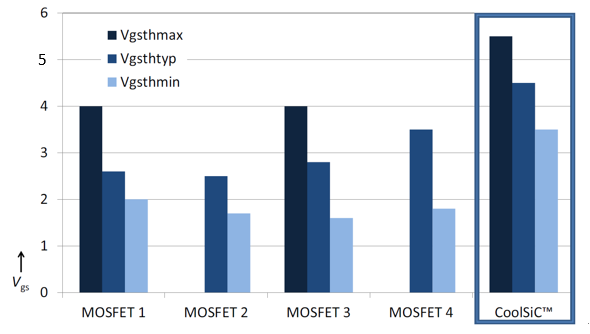
First of all, since SiC MOSFET devices need to work in high-frequency switching applications, the impact they face due to parasitic parameters is more significant. Since the SiC MOSFET itself has a low gate turn-on voltage, it is more likely to be mistakenly turned on due to circuit crosstalk in actual systems, so it is generally recommended to use gate negative voltage turn-off. The gate turn-on voltage parameters of different SiC MOSFET devices are listed in Figure 1.

Figure 1 Comparison of gate turn-on voltage parameters of different SiC MOSFETs
In order to improve the ease of use of SiC MOSFETs in practical engineering, at the beginning of the design of SiC MOSFETs, various semiconductor manufacturers will try to adjust the compromise of parameters as much as possible, so that the driving characteristics of SiC MOSFETs are close to the traditional silicon IGBTs familiar to users. However, wide-bandgap semiconductor devices have their particularities. Taking the Infineon CoolSiC â„¢ series as an example, it can be seen from the specifications and application guides that combined with the comprehensive consideration of switching frequency and life calculation, 15V gates can be used in certain applications The turn-on voltage and the gate turn-off voltage are at least -5V. When we turn our attention to other brands of SiC MOSFET devices on the market, we will find that the recommended gate operating voltages vary from company to company. Therefore, an ideal driver chip suitable for SiC MOSFETs should be able to cover a variety of different gate turn-on and turn-off voltage requirements. At least the power supply voltage drop Vpos-Vneg of the driver chip can reach 25v.
Although the SiC MOSFET has a small gate capacitance, the required driving power is significantly smaller than that of the traditional IGBT, but the size of the driving current is closely related to the operating speed of the switching device. Select a driver chip with a large peak output current for SiC MOS, and if the output pulse has both a sufficiently fast rise and fall speed, the driving effect is more ideal, which means that the rise and fall time parameters of the driver chip are required to be compared small. î—’
î—
2. Meet the requirements of shorter dead time setting
In the bridge circuit structure, the setting of the dead time is a key factor affecting the reliable operation of the system. The switching speed of SiC MOSFET devices has been greatly improved compared to traditional IGBTs. Many practical engineering uses hope to further increase the operating frequency of the devices, thereby increasing the system power density. This also means that the system design requires a smaller dead time setting to match it. At the same time, choosing a shorter dead time can also ensure that the inverter system has a higher output voltage quality.
In the calculation of the dead time, in addition to the on and off time of the switching device itself, especially the switching time under low current, the transmission delay of the driver chip also needs to be considered. Especially for the switching device with its own fast switching speed, the delay of the chip accounts for a larger proportion in the consideration of the dead zone setting. In addition, in the isolated drive design, the one-for-one drive method is usually adopted. Therefore, the parameter matching differences between chips also need to be considered when setting the dead zone. To meet the requirements of a smaller dead time, when selecting a driver chip, the corresponding reference chip itself transmission delay time parameter and chip-to-chip matching delay are required.
3. The protection function of the chip
1) Short circuit protection
SiC MOSFETs differ from traditional silicon MOSFETs in short-circuit characteristics. Taking Infineon's CoolSiC â„¢ series as an example, the full series of SiC MOSFETs have a short-circuit withstand capability of approximately 3 seconds. You can use this feature of the device itself to consider short-circuit protection in the drive design to improve system reliability.
Different types of SiC MOSFETs have different short-circuit withstand capabilities, but the shorter the short-circuit protection response time, the better. Drawing on the IGBT desaturation detection method, according to the output characteristics of the switch, the size of the drain-source voltage of the SiC MOSFET can reflect the current change. Compared with silicon IGBT, there is no obvious transition between the linear region and saturation region of the output characteristic curve of SiC MOSFET. The current rise is still fast when short circuit or overcurrent occurs, which means that the protection circuit needs a faster response speed for protection.
For the short circuit protection requirements of SiC MOSFET, it is necessary to select a driver chip with fast detection speed and short response time to design the protection circuit.
In addition, according to the design experience of the IGBT, each time it is turned on, it is necessary to set a blanking time to avoid DSAET false triggering caused by the Vce voltage falling from a high level in the early stage of turn-on. The need for blanking time poses more severe challenges to the short circuit protection circuit design of SiC MOSFETs with only 3us. The DESAT-related parameters of the driver chip need to have higher accuracy to achieve effective protection design. At the same time, the PCB design of the drive circuit needs to be optimized to ensure the influence of smaller loop parasitic inductance.
2) Active Miller clamp
As mentioned earlier, the low gate turn-on voltage of SiC MOSFETs, coupled with its small parasitic capacitance, is also more sensitive to the parasitic parameters of the drive circuit and is more likely to cause false triggers. Therefore, it is often recommended to use negative pressure for shutdown. But at the same time, due to the small gate negative voltage range that SiC MOSFET can withstand, excessive negative voltage spikes may break through the switch tube. Some manufacturers recommend higher negative voltage shutdown, even 0v shutdown. In this case, in order to ensure that the device will not be triggered by the Miller effect during the off period, a driver chip with active Miller clamping function can be used for design.
4. Chip anti-interference (CMTI)
The driver chip used with the SiC MOSFET is in a high-frequency application environment, which requires the chip itself to have a higher anti-interference degree. The parameter commonly used to evaluate the immunity of the driver chip is CMTI. In the current standard, the measurement method for the immunity of magnetically isolated driver chips takes into account the voltage rise and fall dv / dt, which is very similar to the actual operating characteristics of the very fast turn-on and turn-off of SiC MOSFE, so the CMTI parameter It can be used as a technical reference to measure the immunity of the driving chip used to drive SiC MOSFE.
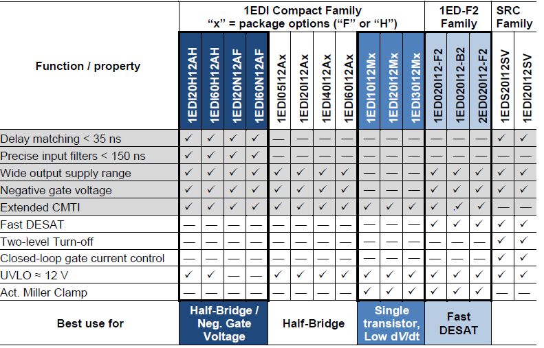
In summary, in order to give full play to the high-frequency characteristics of SiC MOSFETs in practical applications, it is necessary to select a drive with a suitable drive voltage and drive current to meet the small transmission delay of the short dead time design and the matching delay between chips chip. At the same time, effective protection functions and anti-interference can meet higher system reliability requirements. Table 1 compares the relevant parameters of the EiceDRIVER â„¢ series of Infineon's magnetic isolation driver chips. The full range of products provides users with various personalized choices.

Rf Coaxial Cable,Digital Coaxial Cable,Coaxial Cable For Internet,Coaxial Cable Types
Zhejiang Wanma Tianyi Communication Wire & Cable Co., Ltd. , https://www.zjwmty.com
