
Classification diagram analysis of electronic circuit diagrams Electronic circuit diagrams have schematic diagrams, block diagrams, assembly drawings, and plate layouts.
1. Schematic diagram The schematic diagram is a circuit diagram used to embody the working principle of electronic circuits, and is also called "electric schematic diagram". This kind of diagram is generally used in the design and analysis of circuits because it directly reflects the structure and working principle of electronic circuits. When analyzing the circuit, you can understand the actual operation of the circuit by identifying the various circuit component symbols drawn on the drawing and the connection between them. The figure below shows the schematic of a radio circuit. 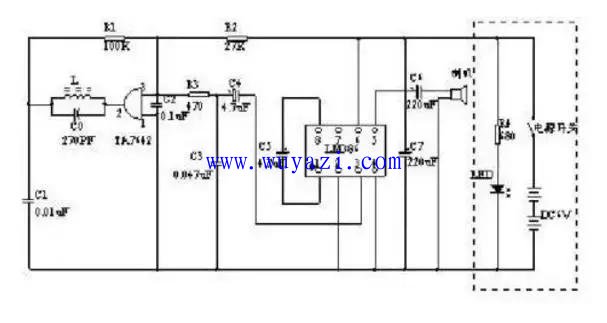
2, block diagram (block diagram)
A block diagram is a circuit diagram that uses blocks and wires to represent an overview of the circuit's operation and configuration. Fundamentally, this is also a schematic. However, in this drawing, there are almost no symbols other than boxes and connections. The main difference between the schematic and the above schematic is that all the components of the circuit and their connection are drawn in detail on the schematic. The block diagram simply divides the circuit installation function into several parts, and each part is depicted as A box with a simple textual description in the box, with a line between the boxes (sometimes with a line connecting the arrows) to illustrate the relationship between the boxes. Therefore, the block diagram can only be used to reflect the general working principle of the circuit, and the schematic diagram can be used as the basis for collecting components and making circuits, in addition to indicating the working principle of the circuit in detail. The figure below shows a block diagram of the above radio circuit. 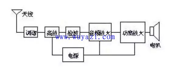
(3) Assembly drawing It is a drawing used for circuit assembly. The symbols on the drawing are often the outline drawing of the physical components of the circuit components. We only need to follow the picture on the picture, and we can complete the assembly of the circuit by connecting some circuit components together. This circuit diagram is generally intended for beginners.
The assembly drawings vary according to the assembly template. Most of the cases used as electronic products use the printed circuit boards described below, so the plate layout is the main form of assembly drawings.
In the beginning of electronic knowledge, in order to get in touch with electronic technology earlier, we chose a screw plate as the basic installation template, so the installation diagram becomes another mode. As shown below: 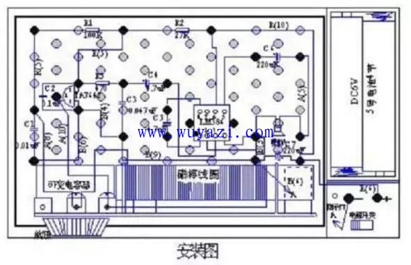
(4) The full name of the printed board map is “printed circuit board diagram†or “printed circuit board diagramâ€. It is the same type of circuit diagram as the assembly drawing, which is used for assembling the actual circuit.
The printed circuit board is covered with a layer of metal foil on an insulating board, and then the metal foil which is not needed for the circuit is etched away. The remaining part of the metal foil serves as a connection line between the circuit components, and then the element in the circuit The device is mounted on the insulating board, and the remaining metal foil on the board is used as a conductive connection between the components to complete the circuit connection. Since the metal on one or both sides of the circuit board is copper, the printed circuit board is also called a "copper clad". The component distribution of the plate map is often quite different from that in the schematic. This is mainly because, in the design of printed circuit boards, it is mainly considered whether the distribution and connection of all components are reasonable, and the printed circuit boards designed by combining these factors should be considered in consideration of factors such as component volume, heat dissipation, anti-interference, anti-coupling, and the like. It is difficult to see from the outside and the schematic is exactly the same; in fact, it can better realize the function of the circuit.
With the development of science and technology, the production technology of printed circuit boards has been greatly developed; in addition to single-panel and double-panel, there are also many panels, which have been widely used in daily life, industrial production, national defense construction, aerospace industry, etc. field.
In the four forms of circuit diagrams introduced above, the electrical schematic diagram is the most common and important. It can understand the schematic diagram, and basically grasps the principle of the circuit, draws the block diagram, designs the assembly diagram, and prints the diagram. It's easy. It is very convenient to master the schematic diagram and carry out the maintenance and design of the electrical appliance. Therefore, the key is to master the schematic.
Pin Header Connector,Pin Header Female,Male Header Pins,Right Angle Pin Header
Cixi Xinke Electronic Technology Co., Ltd. , https://www.cxxinke.com