This paper firstly introduces the structure and working principle of the servo system. Secondly, it introduces the structural block diagram and system composition of the electronic cam. Finally, it introduces the servo implementation and application of the electronic cam.
The composition of the servo systemFrom the basic structure, the servo system is mainly composed of three parts: controller, power drive device, feedback device and motor (Figure 1). The controller adjusts the control amount according to the difference between the given value of the numerical control system and the actual operation value detected by the feedback device; the power drive device acts as the main loop of the system, and on the one hand, the power in the grid is applied to the motor according to the magnitude of the control amount. On the other hand, the size of the motor torque is adjusted, and on the other hand, according to the requirements of the motor, the constant voltage constant frequency power supply system is converted into the AC or DC power required by the motor; the motor is driven by the size of the power supply.

The main components in Fig. 1 vary, and any part of them can constitute different kinds of servo systems. According to the type of drive motor, it can be divided into DC servo and AC servo; According to different controllers, it can be divided into analog servo and digital servo; According to the number of closed loop in the controller, it can be divided into Open-loop control systems, single-loop control systems, dual-loop control systems, and multi-loop control systems.
How the servo system worksThe servo system is an automatic control system that changes the position, orientation, and status of the object such that the controlled variable can follow any change in the input target, that is, the servo system is a closed loop automatic control system with feedback. It consists of a computer digital control system, servo drives, servo motors, speed and position sensors. The computer digital control system is used to store the parts processing program, perform various interpolation operations and software real-time control according to the information fed back by the encoder, and sends out various control commands to the servo drive system of each coordinate axis. After the servo driver and servo motor receive the control command of the computer digital control system, the power is amplified, transformed and regulated, and the speed can be quickly and smoothly adjusted, and the position control can be performed accurately.
Electronic cam system structure diagram
This model uses a resolver as a position sensor and can communicate via a communication port with a PC or a Handy terminal. The PC and the handheld programmer are provided to the user for programming use, providing the user with a convenient programming interface. The signal output adopts two ways of parallel (PIO) and serial (SIO). The output signal can be directly used to control the servo motor and stepper motor driver, and the controller can also centralize the signal and control the inverter and other drive devices. To achieve the purpose of motion control.
Servo implementation of electronic camCompared to mechanical cams, electronic cams are relatively unfamiliar to most people, but the advantages of electronic cams far exceed those of mechanical cams. Served as an electronic cam with servo motor + servo driver + control circuit system, now share the process experience to everyone.
Servo motor with electronic cam function in the country or no, or very few, had visited Google, Baidu. There is little information in this area. There may be many shortages or naiveties for me to explore for myself. Please ask experts to criticize and guide. Servo motor to achieve electronic cam function is divided into two cases (servo control is best to use the operation + direction control mode):
First: No follow-up (no auxiliary encoder or servo motor running following auxiliary encoder, direct control of servo with controller)
This situation is relatively simple, you can use the cycle to send a command to the servo drive to make the servo motor run a variety of curves, define a timer in your control system, define a cam table, calculate the cam according to different curves The data in the table and the CAM table is each time the timer interrupt fills in the timing value, so that a command is sent at the time of the interruption, and at the same time, the timing value is modified in the CAM table according to the internal counting index. Here is how to generate a cam table at a critical time and create a virtual spindle. Also don't forget to record the index of the cam table at power down.
Second: In the following situation (with auxiliary encoder, spindle follows slave axis)
This situation is relatively complicated. The main idea is that according to your curve, the cam table is generated. Your control system receives the signal from the axis encoder and judges the positive and negative rotation by hardware or software. Counting through the CAM table to find out this pulse command corresponds to how many pulse commands to send to the servo controller, pay attention to the issue of forward and reverse. This needs to be done when your slave axis moves at a uniform speed. This is almost the same as the first case. When the slave axis is moving at a variable speed, there will be excessive noise in the servo motor and a serious problem of heat generation. You can optimize it by adjusting the servo drive parameters. Please refer to the servo manual for details. Of course, in the case of sufficient funds, an encoder with a high number of lines can be used, and at the same time it can be multiplied by the program. Also don't forget to record the index of the cam table at power down, or use an absolute encoder (better).

Electronic cams can be applied in various fields such as automobile manufacturing, metallurgy, machining, textiles, printing, food packaging, water conservancy and hydropower.
For example, in machining, replacing the bulky mechanical cam with an electronic cam is, of course, the simplest. The mechanical cam on the motor shaft is replaced with a resolver for position feedback, and the signal of the electronic cam is sent to the controller to realize the full functions of the original mechanical cam. There is no doubt that the system using electronic cams has higher processing precision and flexibility, which can greatly improve the production efficiency.
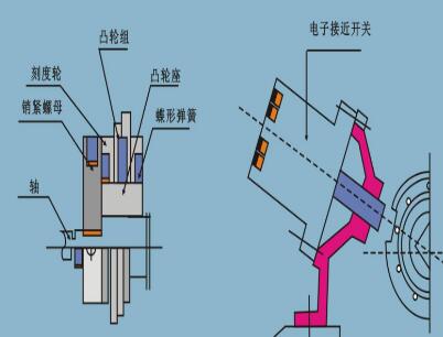
In terms of water treatment and water conservancy and hydropower, electronic cam also has its special application value. As shown in the figure, a buoy is mounted on the sensor (usually the resolver) of the electronic cam, and the buoy is placed on the water surface. The buoy moves up and down along with the change of the water surface and drives the sensor shaft to move together. The revolving position corresponding to the target water level is set to the OFF angle of the cam DOG, and the resolving position corresponding to the highest permissible water level is set to the starting (ON) angle of the cam DOG. The water level sensor signal is sent to the cam controller and the controller controls the pull gate motor. In this way, when the water level reaches the highest water level, the sensor will feedback the water level information to the cam controller, and then control the pull-out motor driver to flood; when the target water level is reached, the cam output signal turns over and the motor opens to achieve a stable water level.
Of course, water level control is not the only use of electronic cams, and flow control tends to be more important. Since the electronic cam can output CAM+POSITION, that is, the cam and position information, the water level sensor can accurately feedback the water level to the cam controller in the control, and if an encoder is installed on the pull motor, the flood discharge can be realized. The precise control of the flow. And this is often the most important. In addition, the serial communication port provided by the electronic cam can communicate with the PC so that remote control can be realized.
In the printing industry, electronic cams have also been widely used and their control is roughly as shown. The resolver is mounted on the drive motor shaft. The resolver feedbacks the position and speed information of the motor to the electronic cam. The electronic cam outputs the speed of the drive motor and the cam signal to the paper feed motor driver to achieve synchronization between the paper feed and the drive. In addition, since the electronic cam has a speed sensing function, it can realize constant speed feeding like servo. In addition, the controller can communicate with the computer, making the control more intelligent.
In the field of mining and metallurgy, electronic cam also has its extensive application. The following figure shows a typical mining equipment, mining from ore deposits to ore storage and mineral transport in the port, the entire process is transmitted by the electronic cam positioning, rotation angle Set and monitor, mineral hopper lift control.
In addition, electronic cams can also be used in spring-like machines, woodworking machines, and automatic painting lines.
The electronic cam product series is moderately priced, stable in performance, flexible in use, and has broad application prospects.
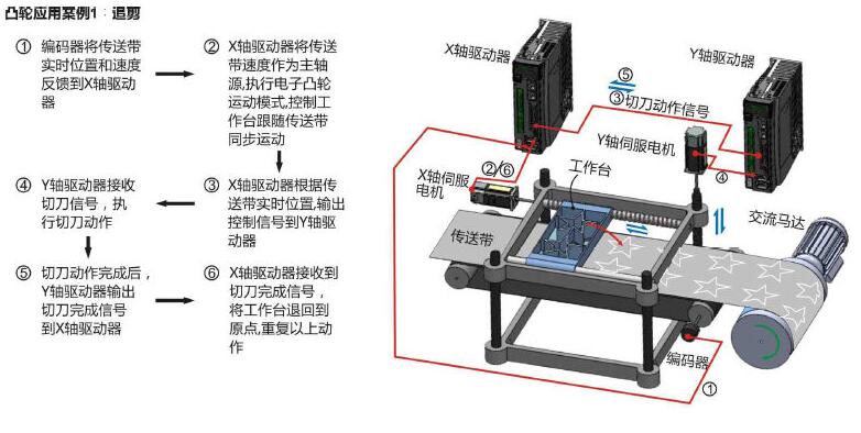
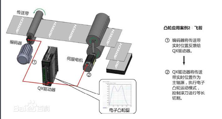
Electronic cam application case

Regular GFCI Receptacle Outlet
Lishui Trimone Electrical Technology Co., Ltd , https://www.3gracegfci.com
