System composition and working principle
Hardware circuit design
System software design
System test
solution:Interrogation unit design and signal post-processing unit design
System software design
The research on vehicle identification system began in the 1970s. The earliest use of optical and infrared technology, its environmental adaptability is poor, and the maximum speed limit of the vehicle is 70km / h, has been gradually eliminated.
SAW technology is an emerging identification technology. It adopts the coded SAW sensor as the ID tag, without any connection, has the advantages of low energy consumption, strong anti-interference ability and small volume, and is especially suitable for non-contact measurement of high-speed moving vehicles under strong electromagnetic interference environment.
This paper designs an automatic vehicle identification system based on SAW technology, which can be applied to non-stop vehicle identification, which provides an efficient solution for highway vehicle toll collection system. The vehicle identification distance is 10m and the maximum speed is 120km/h. The identification code is 32 bits long and the number of identifiable vehicles is 232. The system works in the wild environment around the clock.
System composition and working principleThe vehicle identification system consisting of a SAW sensor consists of a SAW sensor tag mounted on a high-speed moving vehicle, an interrogation unit with an active antenna, and a signal post-processing unit. As shown in Figure 1.
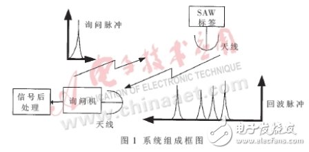
The SAW tag consists of a sensor antenna, a piezoelectric substrate, an interdigital transducer, and a reflector that is encoded in vitro by the sensor.
The sensor antenna receives the interrogating electromagnetic pulse signal sent by the remote interrogator, converts it into a surface acoustic wave through the interdigital transducer, forms an echo after encountering the reflective strip, and the echo is reconverted into electromagnetic wave through the interdigital transducer and Launched again through the antenna. These echo signals form a sequence of pulses determined by the number and position of the reflective strips on the surface of the crystal, which is similar to the bar code pattern, and the time delay of each pulse depends on the SAW propagation speed. The signal post-processing unit estimates the pulse delay variation and demodulates the identification code in real time.
Hardware circuit designa. Inquiry unit design
Figure 2 is a block diagram of the interrogation unit. It consists of a transmitter, a receiver, a local oscillator module, and so on.
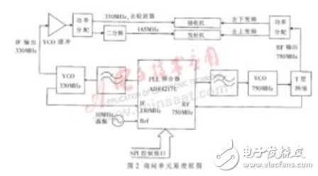
Local Oscillation Module: Three frequencies are required in this system, namely 750MHz, 330MHz and 165MHz, which are generated by the frequency synthesizer. The frequency synthesizer adopts AD's ADF4127L, which is a current-type dual-frequency synthesizer. It can provide two frequencies of RF/IF. It is controlled by SPI interface and its internal registers are configured through FPGA chip.
The output frequency produced by the ADF4127L is locked by the VCO at 330MHz and 750MHz. The 330MHz VCO uses the MAX2608, which produces frequencies from 300MHz to 500MHz. The 750MHz VCO uses Mini's Pos-1050 with a frequency range of 685MHz to 1025MHz.
The 750 MHz signal is supplied to the upconversion of the transmitter and the downconverting portion of the receiver front end via the power splitter, respectively. The 330 MHz signal is supplied to the detector of the receiver, and the other channel is divided by two to produce a 165 MHz frequency. The power splitter uses Mini's LRPS-2-4J, which has a very low voltage standing wave ratio. The second-frequency selection uses Microwave's low-noise two-divider HMC361S8G.
Transmitter: The FPGA generates a 40ns time window to intercept the 165MHz carrier, broadens its spectrum, generates a pulse signal with a center frequency of 165MHz and a bandwidth of 50MHz, and sends it to the SAW expander to form a chirp. The SAW expander uses a surface acoustic wave dispersion delay line produced by Nanjing 54 with a bandwidth of 20 MHz. The expanded pulse has a bandwidth of only 20 MHz and the expander attenuates by 30 dB. This signal is amplified by the AD8353 IF amplifier and upconverted to 915MHz with the 750MHz local oscillator. The out-of-band clutter is filtered by the RF bandpass filter, and then preamplified by the MAX2235. The antenna is transmitted out to form an interrogation signal. The upconverter chip uses the MAX2671, and its RF output range is 400MHz~2500MHz. The RF bandpass filter uses the F5CE-D2 series of SAW bandpass filters. It uses a special DMS dual-mode SAW technology with excellent out-of-band attenuation and passband flatness, which is widely used in mobile communications.
After the inquiry signal is transmitted, the antenna switch immediately hits the receiving position to prepare for reception. The switch uses Mini's KSWHA-1-20, which is a GsAs switch with high isolation and switching speed of 3ns.
Receiver: The design of the superheterodyne receiver is adopted, as shown in Figure 3.
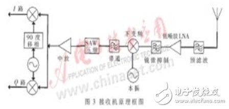
When the echo signal arrives at the front end of the receiver, it is first filtered. There are two RF filters in the receiver: a pre-select filter and an image rejection filter. The pre-selection filter filters out unwanted signals to prevent saturation of the RF front end and crosstalk. The image rejection filter suppresses the first image frequency, the half intermediate frequency, and the local oscillator spurious response. The RF filter is FAR-F5CE-915M00-D236. After filtering, the signal is amplified by the RF amplifier MAX2642, which is a low-noise amplifier that provides an input IP3 of 0dBm with a noise figure of 1.3dB.
After RF filtering and amplification, the signal is downconverted with the local oscillator 750MHz. The down-conversion chip uses the MAX2682, which uses a double-balanced mixer structure with an input frequency of 400MHz to 2500MHz. After down-conversion, the signal enters the intermediate-frequency SAW filter for intermediate-frequency filtering, and then passes through the SAW compressor to output the compressed pulse. The compressed signal is amplified by the AD8353 intermediate frequency and sent to the orthogonal down-conversion to demodulate the I and Q signals. The RF2721 is a quadrature demodulator designed by RF for digital mobile receivers that recovers in-phase and quadrature baseband signals from amplified and filtered IF signals.
b. Signal post-processing unit design
The block diagram of the signal post-processing unit is shown in Figure 4.
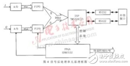
The in-phase component I and the quadrature component Q which are orthogonally down-converted from the interrogation unit are filtered out by the low-pass filter, and then converted into digital quantities by the 8-bit analog-to-digital converter AD9058, which is buffered by the FIFO. , sent to the DSP for calculation. The FIFO is selected by HBA's FQV251, and the DSP uses TI's floating-point processor TMS320C33. The I and Q signals are demodulated signals sent by the receiver, which carry the identification information of the identification card, and the format of the identification code is 32 bits. When the clock is synchronized, the correlation processing algorithm of the soft decision is adopted, that is, whether the current bit is 0 or 1 according to whether the square sum of the two signals exceeds the threshold.
The FPGA is responsible for the generation of various control signals. The EPM7032 of ALTERA's MAX7000 series is used to provide 5000 available gates. EPROM selects STC's 27C256.
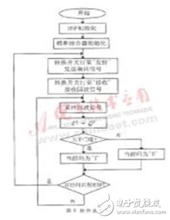
System software designThe software flow is shown in Figure 5. After the system starts working, the DSP initializes and the FPGA configures the frequency synthesizer ADF4127L to generate a precise frequency source. The interrogator switch is pointed to the transmitting position, and the transmitting unit transmits the interrogation pulse signal. After a period of time, the switch points to the receiving position, the receiving unit receives the echo signal, performs A/D sampling first, and squares the sampling values ​​of the I and Q paths. Adding, if it is greater than the encoding threshold, it determines that the current code is 1, otherwise it is 0. After a frame of 32-bit identification code is discriminated, the interrogation unit re-issues the interrogation signal and cycles through. The demodulated identification code is sent to the external device through the serial port for processing.
The system has been tested several times in highway toll stations and parking lots. The test results show that the system can work around the clock, can accurately identify high-speed sports vehicles within 10m distance, speed up the speed of vehicles passing through toll stations, relieve traffic tension to a certain extent, and reduce the cost of toll stations.
Looking for a new, improved and longer lasting vape experience? Look no further than Fume Extra. Prefilled with a larger 6ml flavor pod and powered by a 850mAh built-in battery designed to give you 1500 puffs. It`s long lasting without adding any unnecessary bulk. Sleek, compact and pocket-friendly, Fume Extra will never hold you back from puffing on the go.
Fume Extra Vape,Fume Extra,Fume Vape,Fume Extra Vape Pod
Shenzhen Kate Technology Co., Ltd. , https://www.katevape.com
