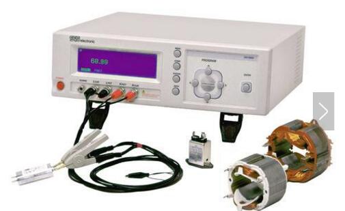
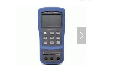
LCR tester, L: Inductance (to commemorate physicist Heinrich Lenz), C: Capacitor, R: Resistance, LCR digital bridge is an instrument that can measure inductance, capacitance, resistance, and impedance.
With the development of modern analog and digital technologies, the LRC bridge has been eliminated, but the name of the LCR bridge has been in use ever since. If it is a LCR bridge using a microprocessor, it is called an LCR digital bridge. The average user also calls these: LCR tester, LCR bridge, LCR meter, digital bridge, LCR Meter and so on.

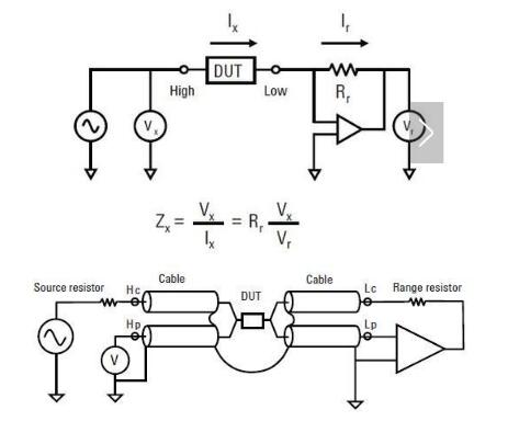
Both Vx and Vr are vector voltmeters, and Rr is an ideal resistor. The self-balancing bridge means that when the DUT (Device Under Test) is connected to the circuit, the negative feedback configuration of the amplifier automatically causes the OP input to be virtual ground. Vx accurately measures the voltage across the DUT (the Low potential of the DUT is 0), and Vr and Rr measure the DUT current Ix, from which Zx can be calculated.
The test terminals Hp, Hc, Lp, Lc of the HP4275 (subscript c stands for current, subscript p stands for Potentail), and the configuration of Guard (ground) can cause differences in test errors.
The way to improve accuracy is:
1, Hp, Lp, Hc, Lc as close as possible to the DUT;
2. Reduce the loop area & magnetic flux of the test current Ix (the key is to analyze Ix, and use Guard and Cable to minimize the loop area);
3. Use Gurard and Cable to construct the electric field connection between the ground plane interrupt signal lines, although it will increase the capacitance of the signal line to ground (the capacitance to ground does not affect the test results), but it will reduce the mutual capacitance of the signal lines.
The parasitic impedance (Zhg, Zlg) of Guard and Cable does not affect the test results. The voltage across Zlg is 0 when the bridge is balanced, and the current flowing to Rr is not shunted by Zlg. The shunt of Zhg does not affect the voltage measurement of Hp. .

LCR testers are typically used to test inductors and capacitors. The measurement steps are as follows:
Set test frequency
Test voltage or current level
Select test parameters such as Z, Q, LS (series inductance), LP (parallel inductor), CS (series capacitor), CP (parallel capacitor), D, etc.
Instrument calibration, calibration mainly for open circuit, short circuit calibration, high-end instrument for load calibration
Select test fixture
Fixture compensation
Place the DUT on the fixture and start the test.

Watch & Apple Airtag Screen Protector
TPU Watch Screen Protector, Transparent ​Watch Screen Protector, Watch Screen Protector Case, Apple Watch Case, Apple Watch Case Protector, Apple Watch Protective Case
Shenzhen Jianjiantong Technology Co., Ltd. , https://www.jjthydrogelprotector.com
