It is easy to find a 100fF capacitor as a parasitic element in your power supply. You must understand that only after processing them can you get an EMI-compliant power supply.
A small amount of parasitic capacitance (100 femtofarads) from the switch node to the input leads will prevent you from meeting electromagnetic interference (EMI) requirements. What does the 100fF capacitor look like? In Digi-Key, there are not many such capacitors. Even if they do, they provide a wide tolerance due to parasitic problems.
However, it is easy to find a 100fF capacitor as a parasitic component in your power supply. Only when they are handled can they obtain EMI-compliant power supplies.
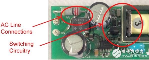
Figure 1 is an example of these unplanned capacitors. On the right side of the figure is a vertically mounted FET with a switch node and clamp circuit that extends to the top of the picture. The input connection enters from the left side and reaches a position within 1 cm of the drain connection. This is the point of failure where the FET's switching voltage waveform can be coupled to the input bypassing the EMI filter.

Figure 1. Switching node and input connections are adjacent, reducing EMI performance
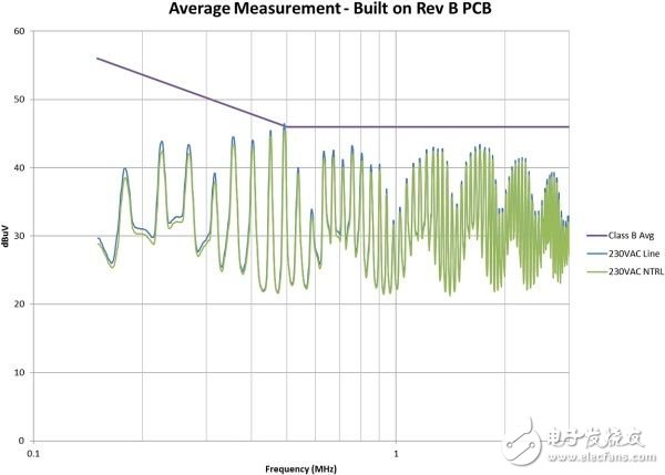
Note that there is some shielding provided by the input capacitor between the drain connection and the input lead. The capacitor's housing is connected to the main ground to provide a path back to the main ground for common mode current. As shown in Figure 2, this tiny capacitor can cause the power supply EMI signature to exceed the specification.

Figure 2. Parasitic drain capacitance results in EMI performance that exceeds specification requirements
This is an interesting curve because it reflects several problems: lower frequency radiation that is clearly beyond the specification requirements, 1MHz to 2MHz components where common mode problems are usually apparent, and attenuation sinusoids for higher frequency components ( x) / x distribution.
Xinxiang Mina Import & Export Co., Ltd. , https://www.mina-motor.cn
