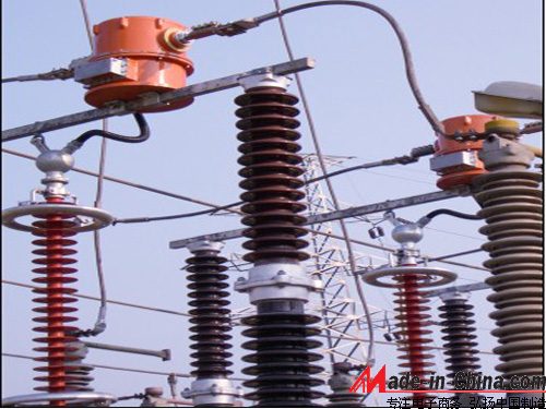
 With the continuous development of the power industry, the voltage level of the power grid is continuously increasing, and the measurement requirements for voltage and current are also increasing. The transformer as an electrical device that connects high voltage and low voltage is also constantly improving and developing. An important indicator of whether the transformer is advanced or not is the insulation of the transformer. For traditional electromagnetic transformers, because the insulation cost increases exponentially with the increase of insulation level, the original air insulation, oil-paper insulation, gas insulation and cascade insulation can no longer meet the insulation requirements of ultra-high voltage equipment. At the same time, there is a problem of magnetic saturation in the traditional transformer, which causes the relay protection device to malfunction or refuse to move. Moreover, the drawbacks of ferromagnetic resonance, flammability and explosiveness, and small dynamic range have always been difficulties that traditional transformers cannot overcome. As a result, various measurement methods for high-voltage, high-current signals have emerged. Among them, measurement methods based on the principles of optics and electronics have become relatively mature and promising for the past 30 years. A method of measurement under ultra-high pressure conditions.
 Photoelectric transformer can be roughly divided into three major parts: high-potential side signal acquisition and processing part, ground potential side signal processing part, and high-potential side power supply part.
The high potential signal acquisition and processing part mainly includes data acquisition, signal processing, A/D conversion, and electro-optic conversion (LED), optical fiber transmission, and insulation. The main function principle is that the current signal obtained by the sensor is input to the signal processing circuit through the acquisition device, and is converted into a digital signal through the multi-channel signal A/D converter. The clock and data signals are converted into optical pulse signals through the LED and transmitted to the low via the optical fiber. The signal receiving part of the potential side.
The ground potential side signal processing part mainly includes a photoelectric conversion circuit (PIN), an amplification and shaping circuit, a logic control circuit, a D/A conversion circuit, and a PC circuit. Its function principle is to pass the clock and data signal transmitted from the high-potential side through the processing of the amplification and shaping circuit, and then the signal required by the user of the power grid under the action of the logic control circuit (generally there are four types: measurement current signal, The protection current signal, supply voltage monitoring signal, and temperature signal of the sensor head are separated and converted to analog signals by the D/A converter; at the same time, the high-voltage end serial optical signal is transmitted to the low voltage side, and the DAT is obtained after the photoelectric conversion circuit. CLK signal. DAT and CLK shift the serial signal into parallel signals through the shift register and issue an interrupt request. The CPU reads the parallel data after responding. After the completion of the reception, the CPU sends the data to the buffer in turn, and the master CPU controls the readout of the digital signal for use by the user.
The power supply part is one of the core parts of the system. Since the sensor head of this photoelectric current transformer is installed on the high potential side and is composed entirely of electronic circuits, there must be a corresponding power supply to the electronics of the sensor head. Circuit. In the system structure diagram, the laser (LD), LD drive current source, optical fiber, photoelectric converter (photocell), and DC/DC converter constitute the power supply part of the system. The laser on the ground potential side transmits the light energy to the photocell through the optical fiber. After the output of the photocell passes through the DC/DC converter, the power required by the electronic circuit (5V or 12V, etc.) can be obtained.
Compared to traditional electromagnetic transformers, photoelectric transformers have obvious advantages:
(1) In the high voltage, high current measurement environment, the optical fiber or optical medium is a good insulator, which can meet the insulation requirements under high-voltage working environment; (2) there is no danger of the traditional open-circuit secondary current transformer generating high voltage, And traditional oil-filled voltage, current transformer leakage, explosion and other hazards; (3) does not produce magnetic saturation and ferromagnetic resonance phenomenon, it is especially suitable for fault diagnosis under high voltage, high current environment; (4) frequency bandwidth , From DC to several hundred kilohertz, suitable for relay protection and harmonic detection; (5) Large dynamic range, can produce high linearity response in large dynamic range; (6) Adapt to the current power system Digital signal processing requirements, it can also be used for high-speed remote sensing, telemetry systems for protection, monitoring and measurement purposes; (7) The entire measurement device is compact, light weight, small size; (8) each function module is relatively independent, easy to install and Maintenance, suitable for networked measurements.
After more than 30 years of development, measurement requirements have gradually increased, and measurement technology has gradually matured. Photoelectric transformers are the mainstream products of the next generation of transformers. Their irreplaceable technological advantages have been highlighted, with the current marketization of photoelectric transformers. The process will certainly bring about revolutionary changes in power system measurement, protection and monitoring.
Photoelectric transformers can use new technologies such as Rogowski coils, low-power current transformers, and series inductance dividers to achieve a current measurement accuracy of 0.1. The voltage measurement accuracy is 0.2. In the structure, fiber optic energy and signal transmission and special solid-state insulating grease vacuum infusion technology are used to enhance the EMI resistance and insulation performance, which greatly improves reliability.
The actual operation shows that the digital photoelectric transformer is safe and reliable; its accuracy is higher, and it is more suitable for digital secondary protection measurement and control devices, especially in the ultra-high voltage, ultra high voltage power grid. With his lower cost advantage, he will have a broad prospect of use.
24v wall charger,24v dc adapter,24v ac dc adapter,24v switching adapter,100-240V AC to DC 24V 3A 72W Power Adapter,12W Ac Switching Power Adapter,24V 0.5A Power Supply For Led Lights
Shenzhen Waweis Technology Co., Ltd. , https://www.huaweishiadapter.com

