introduction
The development of modern automotive electronic technology makes the electronic level of automobiles higher and higher. Although the electronic control system improves the power and economy of the car, the accompanying complicated circuit will inevitably lead to the huge and complicated body wiring. Therefore, improving the reliability, real-time and security of communication between control units has become an urgent problem to be solved. The German Bosch company, known for its R & D and production of automotive electronic products, has developed the CAN bus protocol for this purpose and made it an international standard. The electric power steering (E1ectric Power Steering System, EPS) is a steering system that assists power according to the driver's intention and the operating conditions of the vehicle. The control process of EPS is the process of comprehensive control of the power steering system, so the communication and coordinated control of the EPS electronic control unit and other electronic control units in the vehicle are very important. The introduction of CAN bus technology in the EPS system enables the EPS electronic control unit to communicate with other vehicle-mounted electronic control units to achieve data sharing and coordinate EPS control with other systems.
1 Introduction to CAN bus
CAN is the controller area network. It is a field bus communication structure developed by Bosch to solve many control and data exchange problems in modern automobiles. The maximum speed can reach 1 Mbps (within 40 m) and work in a multi-master mode. Compared with the general communication bus, CAN bus data communication has outstanding reliability, real-time and flexibility, and it is currently the most widely used car network. The CAN bus has the following characteristics:
â‘ The hardware connection is simple, and it has a good performance-price ratio.
â‘¡With quick response capability, it is very suitable for applications with high real-time requirements.
â‘¢High reliability. The error correction capability of the CAN bus is very strong. Each frame of data in the protocol uses CRC and other check measures, and the data error rate is extremely low. If a node has a serious error, it can automatically leave the bus, and the operation of other nodes on the bus is not affected.
2 System hardware design
2.1 Introduction to LPC2129
LPC2129 microcontroller is one of NXP's 32-bit microcontrollers, its internal basic structure includes: central processing unit (CPU), two 16C550 industry standard UART, high-speed I2C interface (400 kHz), two SPI interfaces, 8 Channel input capture / output comparison timer, an 8-channel pulse width modulation module and 46 independent digital I / O ports, there are also 256KB Flash ROM, 16 KB RAM, CAN function block includes 2 compatible CAN2. 0B protocol CAN controller. These rich internal resources and external interfaces can meet the requirements of ECU (Electronic Control Unit) for various data processing and CAN network data transmission and reception. The chip integrates 2 CAN modules, which can realize the gateway node function of high and low speed CAN network.
The CAN module follows the CAN2.0B protocol and integrates all the functions of the CAN bus controller of the acceptance filter. In addition, it uses advanced buffer layout to improve real-time performance and simplify the design of application software.
2. 2 CAN module design
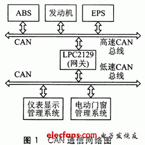
The communication system of the car is composed of EPS control system, ABS system, engine system, power window system, and lamp control system. These electronic control systems have different requirements for real-time response in the entire control system. In addition, a large amount of real-time data exchange is required between many nodes in the actual operation of the car. If all the nodes of the entire car are hung on a CAN network, and many nodes communicate through a CAN bus, once the information management configuration is slightly improper, it is easy to appear that the bus load is too large, causing the system to respond in real time. This is not allowed in the real-time system, so according to different requirements, the automotive network can be divided into two speed levels: high-speed CAN network and low-speed CAN network. ABS, EPS and other nodes have a small number of electronic control units, and require high real-time and stability. They form a high-speed CAN network with a transmission rate of 500 kbps. There are a large number of electric control units for body motors and lamp nodes, and the transmitted data is complicated. The requirements for accuracy and stability are better than real-time. They form a low-speed CAN network with a transmission rate of 125 kbps. For communication between networks of different rates, there must be corresponding gateways for data filtering and rate conversion to achieve data communication between nodes of different rate networks. The high and low speed CAN gateway is implemented with LPC2129, and its communication network is shown in Figure 1.

2. 3 CAN node hardware design
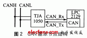
The CAN node hardware circuit mainly includes a microcontroller with a CAN controller and a CAN transceiver for data transmission and reception. This design uses NPC's 32-bit microcontroller LPC2129, which has a CAN controller, which is mainly responsible for CAN initialization and data processing. There are many types of CAN transceivers. This design uses Philips' high-speed transceiver TJAl050. CAN basic node structure is shown as in Fig. 2.

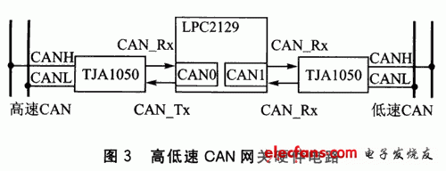
2.4 Hardware circuit design of high and low speed CAN gateway
The main role of the gateway is to coordinate the sharing of data between the various networks, and is responsible for the communication between the nodes. Its hardware structure is very similar to the CAN node. Because it is responsible for data sharing between the high-speed and low-speed networks, it must cross two networks at the same time. The CAN bus gateway hardware structure is shown in Figure 3.

Wire Bending Machine,Crimping Tool,Cable Stripping Crimping Machine,Wire Crimping Pliers
Kunshan Bolun Automation Equipment Co., Ltd , https://www.bolunmachinery.com
