This article will introduce four energy-saving modes under the 802.11 protocol, namely PSM, APSD, PSMP and SMPS. ASPD is designed based on 802.11e. In APSD, the node is divided first and then the uplink and downlink transmission modes. U-APSD can only be used in EDCA mode.
In the main version of 802.11, a total of four energy-saving modes are defined, in addition to the most basic PSM mode, and some details of how it works. Since PSM was designed under the original 802.11 protocol, it uses a more conservative design to ensure the most stable operational requirements. In later versions of 802.11, in order to improve the performance of the energy-saving mode, there have been some other energy-saving modes. This article mainly introduces the three main energy-saving modes: APSD, PSMP and SMPS.
APSD (AutomaTIc Power Save Delivery)The ASPD mode is a direct improvement to the PSM mode. The biggest drawback of the PSM mode is the "ping-pong" mechanism used when requesting data. That is, a polling frame request, a data frame feedback, such a process of alternating back and forth. In the case of more data caches, this design will cause too many polling frames to appear, reducing the actual network transmission efficiency. Therefore, ASPD needs to improve this.
APSD (AutomaTIc Power Save Delivery): ASPD is designed based on 802.11e. Set the concept of a service time in 802.11e, Service Period (SP). We can simply understand that if a node occupies a channel, it sets a service time, and during that time, the node can transmit multiple frames, in other words, a multiple transmission. In ASPD, there are two specific working modes: S-APSD and U-APSD. (PS: This article will not be carried out on the Service Period and the specific working mechanism of EDCA, and its content will be placed in the 802.11e finishing later)
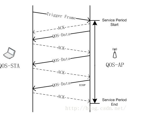
We use the following diagram to first describe the basic idea of ​​APSD:

In the above figure, we assume that there is a QOS-AP with a QOS-STA (PS: Since ASPD is based on 802.11e, both QOS-AP and QOS-STA are devices that support 802.11e). It is assumed that a transmission process is initiated by the QOS-STA, that is, a "Trigger Frame" frame is first sent, and the frame may be a QoS data or a QoS Null frame. Through the frame, the node applies for a service time, that is, a Service Period Start ( PS: The service time can be understood as the TXOP time in 802.11e, instead of the service time used in the network model in general, during the service time, multiple network frames can be transmitted, and then QOS-AP will feed back an ACK and A QOS-Data frame. Next, within the service time range, QOS-STA will continue to exchange data with QOS-AP. After the QOS-AP cache is completely transmitted, the QOS control field in the last QOS-Data frame is marked with EOSP (End Of Service Period), thereby ending a service time, that is, Service Period End. In contrast to the PS-Poll we mentioned in the preliminary energy-saving mode, the former ping-pong mode requests one feedback, while in APSD, multiple frames can be exchanged in one request. Below we explain S-APSD and U-APSD.
S-APSD (Scheduled APSD): Based on the scheduled APSD, S-APSD can be used in both EDCA (DCF extension) and HCCA (PCF extension) modes. From the author's personal point of view, S -APSD is more like an extension of the PSM-PCF mode we mentioned earlier. Since the specific working mechanism of S-APSD is not very good for packet capture, it can only be understood by understanding the literal meaning of the protocol. If there is any error, please forgive me.

As shown in the above figure, it is a working mode of S-APSD. In S-APSD, the SP (Service Period) is pre-scheduled. When the scheduling time is about to arrive, QOS-AP will send a trigger frame, and QOS-STA will wake up to accept the frame in advance, thus opening a service. time. The service time is scheduled by the Schedule Element field in the management frame, so the node can know in advance when it should wake up. In the above figure, the trigger sent by the QOS-AP is the PS-Poll, and then the data is exchanged with the QOS-STA. After the STA feeds back the data to the AP, the AP feeds back the data to the STA, so that the switch alternates until the end of the SP time.
Here, QOS-AP and QOS-STA exchange data in the same order of uplink and downlink, that is, there are some similar "ping-pong" mechanisms here, and the PSMP mentioned later will actually improve this point again.
U-APSD (Unscheduled APSD): U-APSD can only be used in EDCA mode based on non-scheduled APSD. U-ASPD is more like the extension of the previously mentioned PSM-DCF mode.

As shown above, it is the working sequence of U-APSD. In this mode, the QOS-STA first sends a trigger frame (ie QOS-Null) to the AP. When the AP receives the frame, it means the start of a service time, and then the AP and the node exchange data one after another. (PS: As for the service time, whether there will be bakcoff during the alternate transmission of uplink and downlink data, the author currently reads the data is not, but for the original description of the agreement, the author has not yet determined)
In fact, the working mechanism of an SP time, S-APSD and U-APSD are the basic mechanisms. The difference is mainly that the SP time of the S-APSD is implemented. For example, the time is implemented in the beacon frame. The U-APSD is initiated by the node, that is, the scheduling time may be initiated at any time, and may also be mainly arrived. Generally, the S-APSD is initiated by the AP, and the U-APSD is initiated by the node, but this The point is not absolute.
PSMP (Power-Save MulTI-Poll)
In fact, OFDM is introduced from 802.11e, Block ACK, RIFS introduced in 802.11n, frame aggregation, MU-MIMO is introduced in 802.11ac (PS: only AP downlink can use MU-MIMO, uplink is not included). The technology will cause the burst downlink transmission efficiency of the AP to be higher than the uplink access efficiency.
Therefore, from the perspective of energy-saving mode, in APSD, the node is divided first and then the uplink and downlink transmission modes, there is no first uplink and downlink, and the transmission efficiency of the sub-node is high, then the latter is the basic idea of ​​PSMP design.
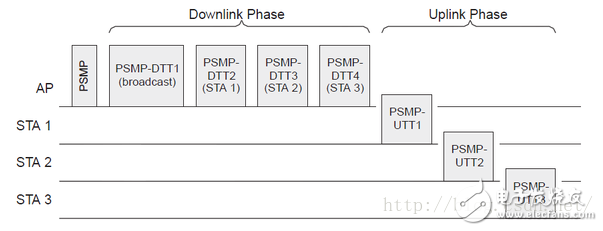
PSMP (Power-Save MulTI-Poll): A new mode added in 802.11n, which can be understood to introduce a stricter scheduling mechanism. It first uses a PSMP frame to schedule the transmission cycle of the entire energy-saving mode, and divides it into PSMP downlinks. Transmission period, PSMP-DTT (PSMP Downlink Transmission Time) and PSMP uplink transmission period, PSMP-UTT (PSMP Uplink Transmission Time). In the PSMP-DTT process, the AP performs burst transmission, where the interframe spacing may be smaller, such as RIFS. The RIFS time will be smaller than the SIFS. The SIFS time includes the switching time from the sending state to the accepting state, and the RIFS is only the switching time between the two sending states. In this process, the node can wake up without the use of CCA, directly in the scheduled time, and accept the data, so that more sleep time can be obtained, thereby saving energy. During the PSMP-UTT time, the node will only wake up during the scheduled period and feed back the uplink data frame, which also reduces the number of listening processes and saves energy. In PSMP, if there is a broadcast/multicast packet in the downlink transmission of the AP, the first data frame will be transmitted within the PSMP-DTT time. This actually transmits the multicast or broadcast frame with the previous PSM mode. the same.
The following diagram illustrates a PSMP timing schedule (refer to "Cambridge.Next Generation Wireless LANs.802.11n")

Then the AP first sends a PSMP frame, which contains the specific scheduling of the downlink and uplink in the subsequent time. Then start to enter the PSMP-DTT time, the first is to send the local cached multicast/broadcast frame (that is, within the PSMP-DTT1 time), and then sequentially send the cached unicast frame corresponding to the node, here PSMP-DTT time, The interframe space can be RIFS for higher efficiency. For the part of ACK, because the author did not do detailed research, it is not described. After the PSMP-DTT time is over, the node will send data frames in its own corresponding uplink scheduling period. For example, STA1 sends uplink data in PSMP-UTT1. When the PSMP-UTT time is over, this round of PSMP data exchange is complete.
PS: The details of some PSMPs are described in Chapter 9 of the book "Cambridge.Next Generation Wireless LANs.802.11n", which is more detailed and interested in reading.
SMPS (Spatial Multiplexing Power Save)Finally, we describe the SMPS mode described in 802.11n, the power-saving mode in multi-antenna mode. In this mode, the node can choose to use the extra antenna to save energy. However, in the actual process, the node is not good at shutting down its own antenna because it cannot determine whether the AP is transmitting data according to the form of multiple spatial streams or in the form of a single spatial stream. If the AP uses multiple streams to send downlink data, and the node is only the working mode of a single antenna, it cannot be received correctly (here, unlike the transmit diversity, if the transmit diversity is also required, the AP needs to transmit according to the diversity mode instead of the space division. In the form of sending, its precoding strategy is different). Therefore, the node needs to close the antenna with the AP to perform appropriate communication, and the mechanism corresponds to the use of the SMPS.
SMPS (Spatial Multiplexing Power Save): In this mode, the node will turn off the extra antenna and use only one antenna to work, thus achieving energy saving. There are two modes in SMPS, one is Static SM Power Save and the other is Dynamic SM Power Save.

The figure above shows the SMPS in a static working mode. We can see that the node says that it needs to send an action frame first, and then switch the AP to a single stream to send the downlink frame, so that the node can save some energy. If you need to restore back to multi-stream working mode, you need to feed back an action frame, which explicitly indicates static mode disabled, so that the frame sent by the AP will be multi-stream mode.

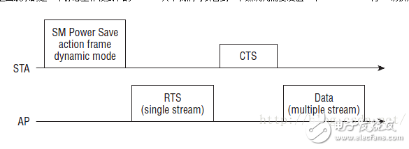
The above figure is the SMPS in dynamic working mode. When the STA sends a dynamic mode action frame, the AP will adopt the single-stream mode in the downlink frame that is fed back. (The downlink frame in the figure is RTS, but it can also be Data Frame). When the frame is fed back, when the AP sends the next frame, it will return to the default multi-stream mode and actively switch back from the single-stream mode. In the static mode, this switch requires a display action frame, so here It is a difference between static and dynamic SMPS.
Waveguide Adaptor,Coaxial To Waveguide Adapter,Waveguide To Coaxial Adapter,Waveguide To Coaxial Transition
Chengdu Zysen Technology Co., Ltd. , https://www.zysenmw.com
