The brushless DC motor is composed of a motor body and a driver, and is a typical mechatronic product. The stator windings of the motor are mostly made into a three-phase symmetrical star connection, which is very similar to the three-phase asynchronous motor. It is used in a wide range of applications and is found in many mechatronic devices.
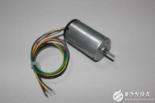
This article is a senior motor control engineer sharing some of his learning about brushless motors.
What is a brushless motor?
The brushless DC motor is composed of a motor body and a driver, and is a typical mechatronic product. Since the brushless DC motor is operated in a self-controlled manner, the starting winding is not added to the rotor like the synchronous motor with heavy-load starting under the variable frequency speed regulation, and the oscillation and the out-of-step are not generated when the load is abrupt. The permanent magnets of the medium and small capacity brushless DC motors are now mostly made of high magnetic energy grade rare earth neodymium iron boron (Nd-Fe-B) materials. Therefore, the volume of the rare earth permanent magnet brushless motor is reduced by one frame number compared with the same capacity three-phase asynchronous motor.
Brushless DC motors use semiconductor switching devices to achieve electronic commutation, that is, electronic switching devices replace traditional contact commutators and brushes. It has the advantages of high reliability, no commutation spark, low mechanical noise, etc. It is widely used in high-end recording stands, video recorders, electronic instruments and automated office equipment.
The brushless DC motor is composed of a permanent magnet rotor, a multi-pole winding stator, a position sensor, and the like. The position sensing commutates the current of the stator winding in a certain order according to the change of the rotor position (ie, detecting the position of the rotor pole relative to the stator winding, and generating a position sensing signal at the determined position, after being processed by the signal conversion circuit To control the power switch circuit, the winding current is switched according to a certain logic relationship). The operating voltage of the stator windings is provided by an electronic switching circuit controlled by the position sensor output.
Position sensors are available in magnetic, photoelectric and electromagnetic types.
A brushless DC motor using a magnetically sensitive position sensor, the magnetic sensing element (such as a Hall element, a magnetic sensitive diode, a magnetically sensitive diode, a magnetoresistor or an ASIC) is mounted on the stator assembly. To detect the change of the magnetic field generated when the permanent magnet and the rotor rotate.
A brushless DC motor using a photoelectric position sensor is provided with a photoelectric sensor device at a certain position on the stator assembly, and a light shielding plate is mounted on the rotor, and the light source is a light emitting diode or a small light bulb. When the rotor rotates, the photosensitive components on the stator will intermittently generate pulse signals at a certain frequency due to the action of the visor.
A brushless DC motor using an electromagnetic position sensor is provided with an electromagnetic sensor component (for example, a coupling transformer, a proximity switch, an LC resonance circuit, etc.) on the stator assembly. When the position of the permanent magnet rotor changes, the electromagnetic effect will cause the electromagnetic sensor. A high frequency modulated signal is generated (the amplitude of which varies with rotor position).
See what this engineer said?
First, I will review a few basic rules: left-hand rule, right-hand rule, and right-hand screw rule. Don't be forced, I will explain it to you below.
The left-hand rule, this is the basis for the analysis of the force of the motor's rotation. Simply put, the current-carrying conductor in the magnetic field will be subjected to force.
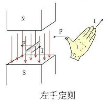
Let the magnetic line pass through the front of the palm, the direction of the finger is the direction of the current, and the direction of the thumb is the direction of the magnetic force. I believe that people who like to play the model have a certain physical basis.
Right-hand rule, which is the basis for generating the induced electromotive force. Contrary to the left-hand rule, the conductor in the magnetic field generates an electromotive force due to the force-pulling of the magnetic line.
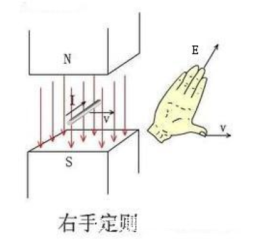
Let the magnetic line pass through the palm, the direction of the thumb is the direction of motion, and the direction of the finger is the direction of the generated electromotive force. Why do you want to talk about the electromotive force ? I don't know if you have a similar experience. Putting the three-phase lines of the motor together and turning the motor by hand will find that the resistance is very large. This is because the induced electromotive force is generated during the rotation of the motor, which generates current and magnetic field. The current flowing through the conductor creates a force that is opposite to the direction of rotation, and everyone feels that there is a lot of resistance to the rotation. Do not believe can try.
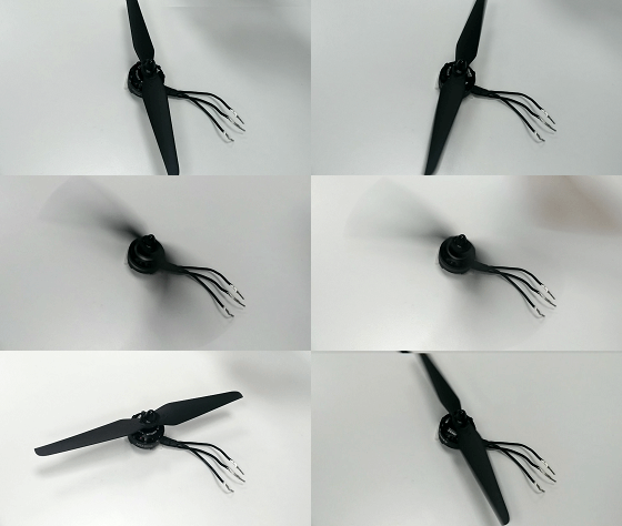
The three-phase lines are separated and the motor can be easily rotated
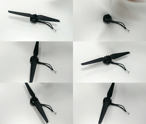
Three-phase line combination, the motor rotation resistance is very large
Right hand screw rule, hold the energized solenoid with your right hand, so that the four fingers bend and current
The direction is the same, then the end pointed by the thumb is the N pole of the energized coil.
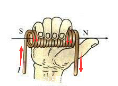
This rule is the basis for determining the polarity of the energized coil, and the direction of the red arrow is the current direction.
After reading the three rules, let's take a look at the basic principles of motor rotation.
Part 1: DC motor model
We found a model of a DC motor that was physics in middle school and conducted a simple analysis by magnetic loop analysis.
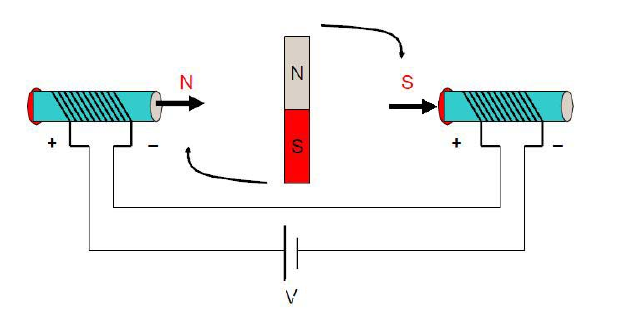
State 1
When the coils of the two ends are energized, according to the right-handed screw rule, the applied magnetic induction B of the direction pointing to the right (as indicated by the direction of the thick arrow) is generated, and the middle rotor tries to make the internal magnetic induction line direction as far as possible. The direction of the magnetic line is consistent to form a shortest closed magnetic line circuit so that the inner rotor rotates clockwise.
When the direction of the rotor magnetic field is perpendicular to the direction of the external magnetic field , the rotor receives the greatest rotational moment. Note that the term "torque" is the largest, not the "force". It is true that when the rotor magnetic field is in the same direction as the external magnetic field, the rotor is subjected to the largest magnetic force, but at this time the rotor is in a horizontal state, the arm is zero, and of course it will not rotate. In addition, the moment is the product of force and force arm. One of them is zero and the product is zero.
When the rotor is turned to the horizontal position, although it is no longer affected by the turning moment, it will continue to rotate clockwise due to inertia . At this time, if the current direction of the two solenoids is changed , the rotor will continue as shown in the following figure. Turn clockwise forward,
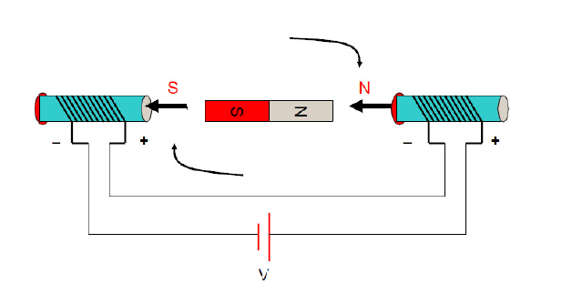
State 2
By constantly changing the current direction of the two solenoids, the inner rotor will keep turning. This action of changing the direction of the current is called commutation. Add a sentence: When to commutate is only related to the position of the rotor, and is not directly related to any other amount.
Part II: Three-phase two-pole inner rotor motor
Generally speaking, the three-phase winding of the stator has a star connection mode and a triangular connection mode, and the " two- phase conduction mode of the three-phase star connection " is most commonly used, and the model is used here for a simple analysis.
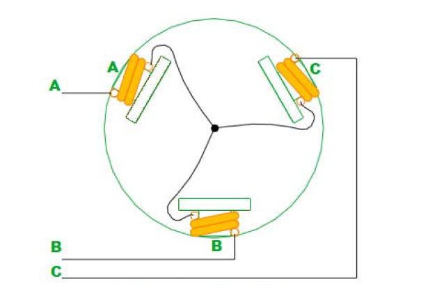
The figure above shows the way the stator windings are connected (the rotor is not supposed to be a two-pole magnet), and the three windings are connected together in a "Y" shape through the center connection points. The entire motor leads to three wires A, B, and C. When two or two are energized between them, there are six cases, namely AB, AC, BC, BA, CA, CB. Note that this is sequential.
Below I see the first stage: AB phase power
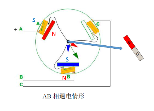
When the AB phase is energized, the direction of the magnetic induction line generated by the A-pole coil is as indicated by the red arrow, and the direction of the magnetic induction line generated by the B-pole is as indicated by the blue arrow, then the resultant resultant force direction is indicated by the green arrow, then Assuming that there is a two-pole magnet, the N-pole direction will coincide with the direction indicated by the green arrow, according to "the middle rotor will try to keep its internal magnetic line direction and the outer magnetic line direction ." As for C, there is nothing for him at the moment.
The second stage: AC phase power
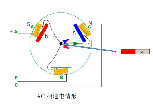
The third stage: BC phase power
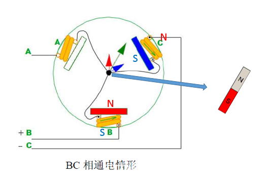
The third stage: BA phase power
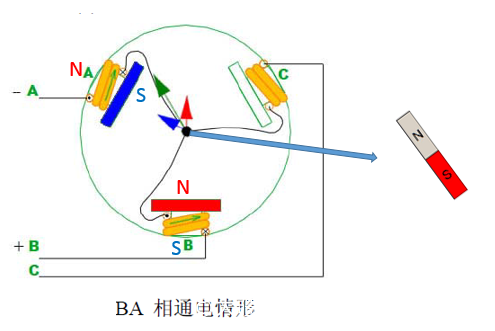
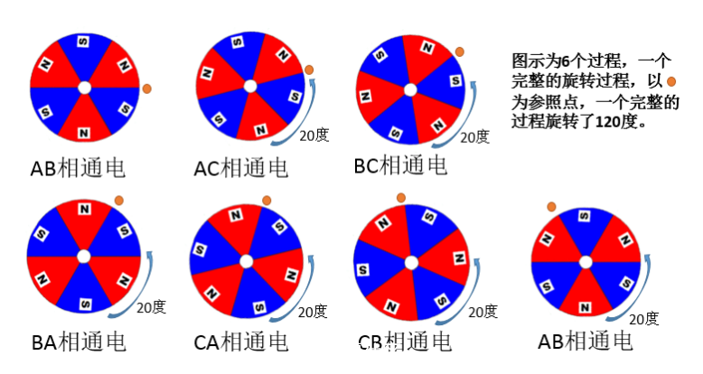
In order to save space, we will not describe the CA\CB model one by one, you can analogize it yourself. The following is a state diagram of the intermediate magnet (rotor):

Rotor rotates 60 degrees per process
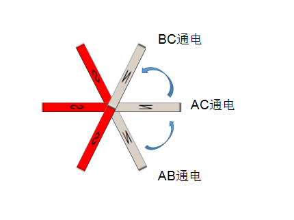
The six processes complete the complete rotation, with 6 commutations.
Part III: Three-phase multi-winding multi-pole inner rotor motor
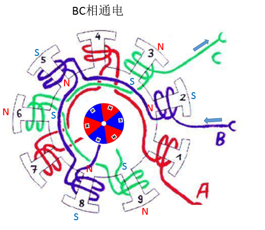
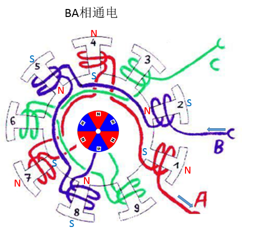
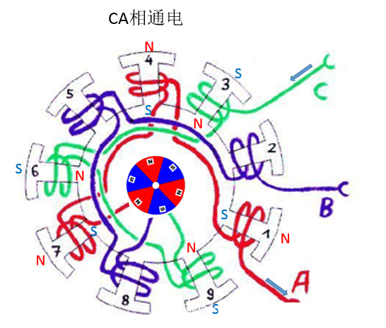
    Let us look at a complicated point. Figure (a) shows a three-phase, nine- winding, six- pole (three-pole) inner rotor motor. The winding connection is shown in Figure (b). It can be seen from the figure (b) that the three-phase windings are also connected at the intermediate point and also belong to the star connection mode. In general, the number of windings of the motor is inconsistent with the number of permanent magnets (for example, 9 windings and 6 poles instead of 6 windings and 6 poles), in order to prevent the teeth of the stator from being aligned with the magnetic steel of the rotor.
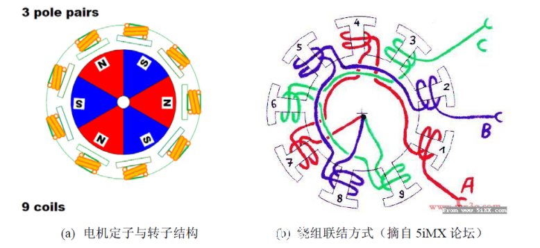
Its movement principle is: N pole and the conduction winding S poles of the rotor have aligned movement trend, while the S pole of the rotor and the N pole with a conduction winding alignment movement trend.
That is, S and N attract each other, and there is a certain difference from the previous analysis method.
Ok, let's help you analyze it again.
The first stage: AB phase power
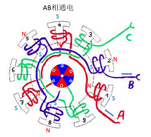
The second stage: AC phase power

The third stage: BC phase power
The fourth stage: BA power
The fifth stage: CA power
The sixth stage: CB power

The above are six different energization states in which five rotation processes have been experienced. Each process is 20 degrees.
Part IV: External rotor brushless DC motor
After reading the structure of the inner rotor brushless DC motor, let's look at the outer rotor. The difference is that the outer rotor motor makes the magnetic steel which is originally in the center position into a piece and sticks to the outer casing. When the motor is running, the whole outer casing is rotating, and the middle coil stator does not move . Compared with the inner rotor, the outer rotor brushless DC motor has a much larger moment of inertia (because the main mass of the rotor is concentrated on the outer casing), so the speed is slower than that of the inner rotor motor, usually with a KV value of several hundred to several thousand. between. It is also the main brushless motor used by the aircraft model.
By the way, let's take a look. The KV value of the brushless motor is defined as: speed / V, which means the speed value of the increase of the idle speed of the brushless motor for each 1 volt increase of the input voltage. For example, an outer rotor brushless motor with a nominal value of 1000 kV, at a voltage of 11 volts, has a maximum no-load speed of 11,000 rpm (rpm means: revolutions per minute).
Brushless motors of the same series with the same dimensions will exhibit different KV characteristics depending on the number of winding turns. The number of turns is large, the KV value is low, the maximum output current is small, and the torque is large; the number of winding turns is small, the KV value is high, the maximum output current is large, and the torque is small. I have previously tested the limit current of the 2204 motor through the machine, the single motor can be 25A, and the 2212 series motor 15A can not go up.
Structure of outer rotor brushless DC motor:

The analysis method is similar to the inner rotor motor. You can analyze it yourself. According to the right-handed spiral theorem, the N/S pole of the coil is judged, and the N pole of the rotor permanent magnet and the S pole of the stator winding are aligned (attractive). The rotor permanent magnet The S pole has a tendency to align (attract) with the N pole of the stator winding, thereby driving the motor to rotate.
Classic brushless motor 2212 1000kv motor structure analysis.
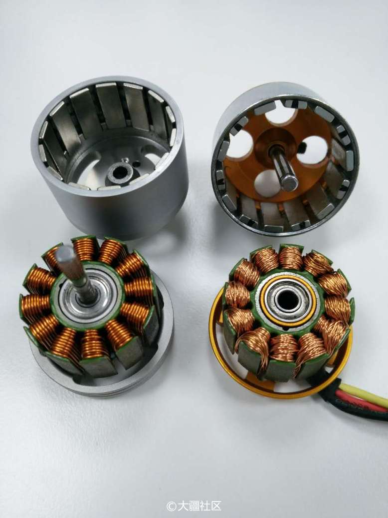
The picture shows the DJI 2312S motor and the XXD 2212 motor (anatomical view)
The structure is as follows: the stator winding is fixed on the base, and the rotating shaft and the outer casing are fixed together to form a rotor, and the bearing is inserted in the middle of the stator.
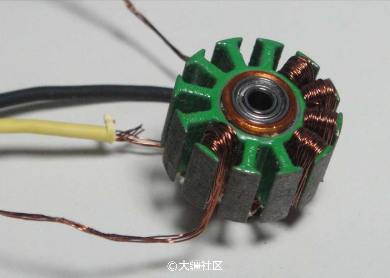
The picture shows the xxd2212 coil disassembly diagram
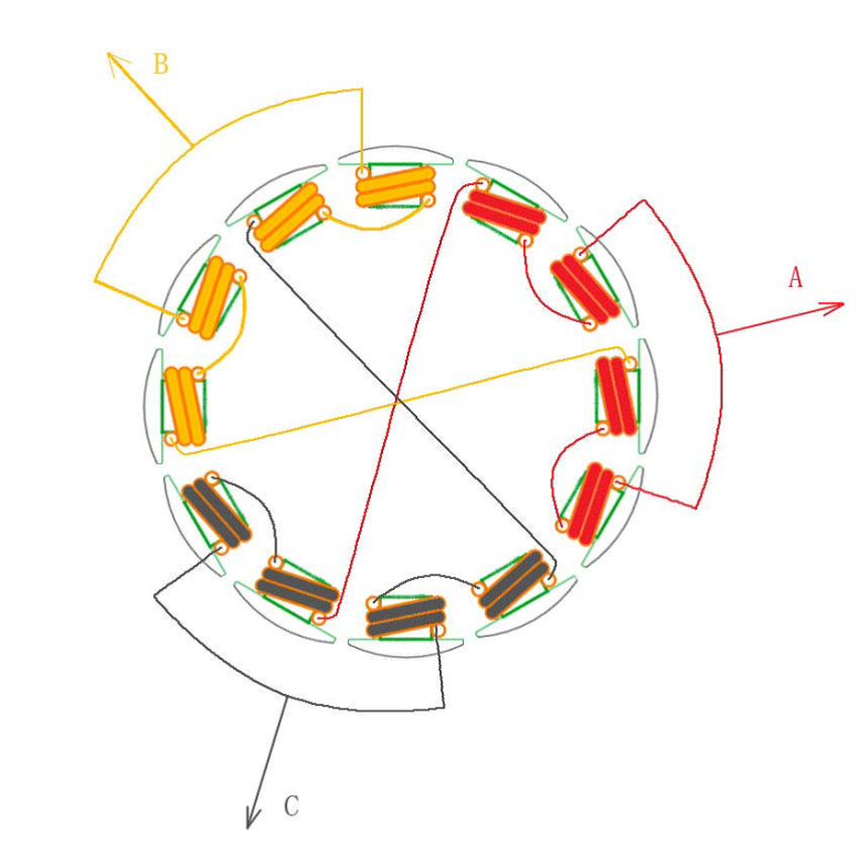
The picture shows 12 windings of 14 poles (ie 7 poles), and the motor windings are wound around.
In the following, six kinds of two-phase energization are shown. It can be seen that although the number of windings and magnetic poles can be varied, the order of energization is actually the same from the perspective of ESC control, that is, regardless of The outer rotor or the inner rotor motor are energized and commutated in the order of AB->AC->BC->BA->CA->CB. Of course, if you want to reverse the motor, the electronic method is energized in the reverse order; the physical method directly adjusts any two lines, assuming A and B are reversed, then the order is BA->BC->AC->AB- >CB->CA, have you found that the order here is completely reversed.
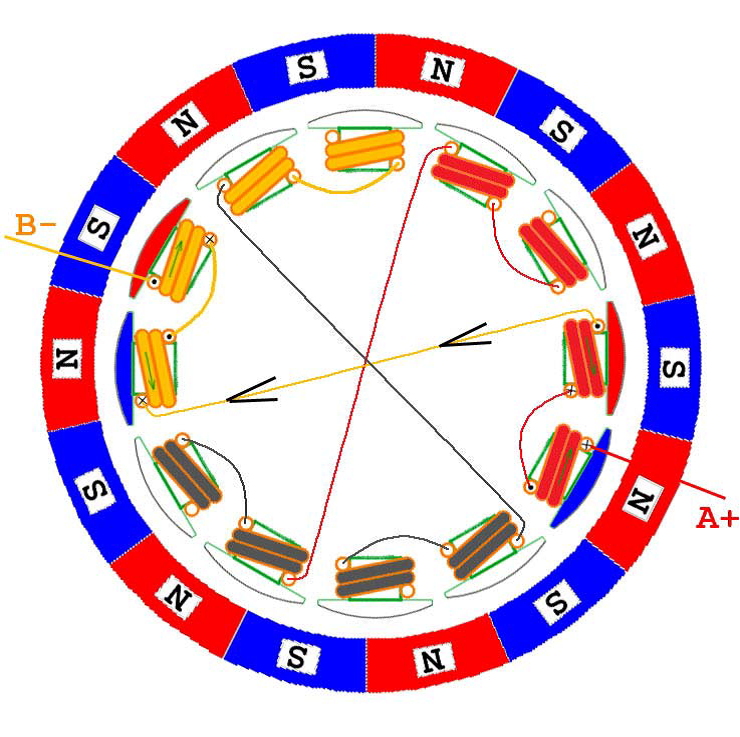
AB phase power
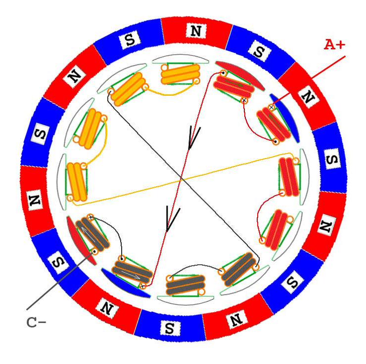
AC phase energization
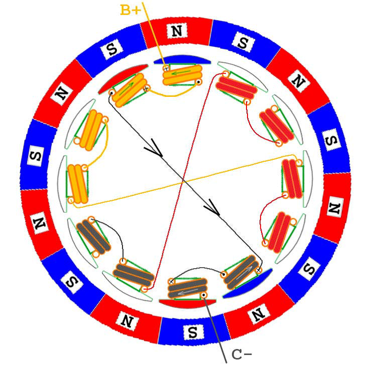
BC phase power
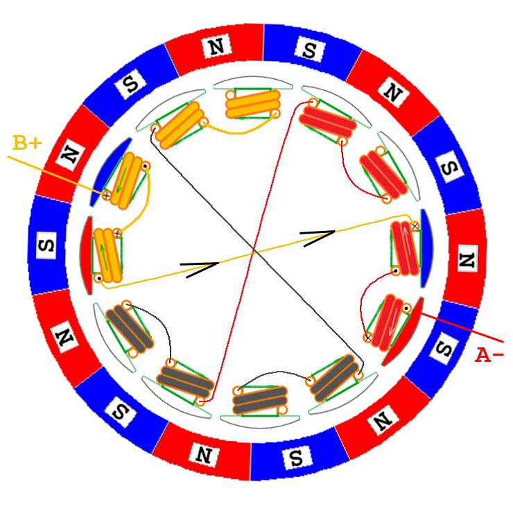
BA phase energization
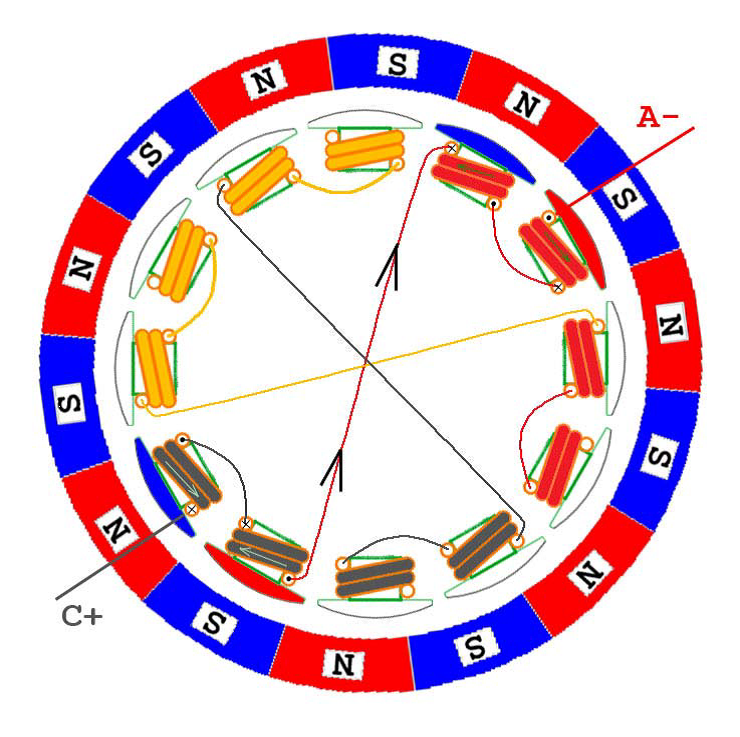
CA phase power
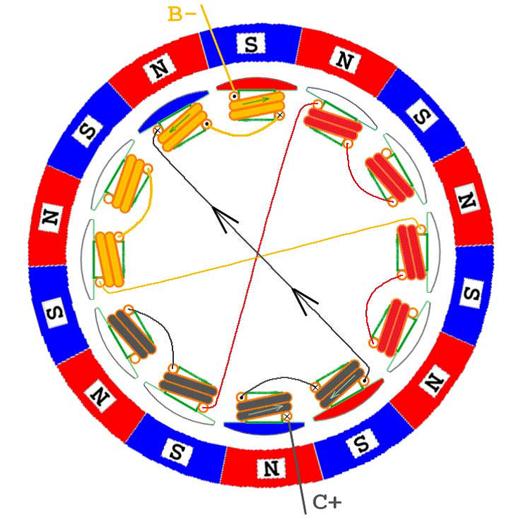
CB phase power
To illustrate, since each lead wire is connected to two windings at the same time, the current is divided into two paths. Here, in order to make the problem as simple as possible, in the following figures, only the current direction of the main circuit is drawn, and one current is not drawn, and the other current is analyzed later, which involves the circuit detecting the commutation position. .
Solar Cells,Solar Cells Silicon,Solar Cells Homemade,Single Monocrystalline Solar Cell
Jiangxi Huayang New Energy Co.,Ltd , https://www.huayangenergy.com
