With the continuous development of technology, various microwave devices have higher and higher requirements on the phase noise of the oscillating signal. At present, the frequency doubling chain method widely used in microwave oscillation sources requires a large amount of additional noise due to the need for multiple frequency doubling, amplification, and filtering. It has a great influence on the phase noise of the microwave oscillation source. The 2856MHz microwave source utilizes both the pulse frequency doubling phase-locked loop and the dielectric oscillator to effectively improve the phase noise of the microwave oscillation source, and has the advantages of low harmonics, small volume, low power consumption and high reliability. It can be used in satellite communication, radar, experimental equipment and other occasions where the phase noise is high.
2 Definition and measurement of phase noisePhase noise is used to characterize the short-term frequency stability of a microwave source. The concept of phase noise can be illustrated by Figure 1.
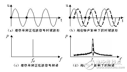
Figure 1 Description of the phase noise concept
When an ideal single-frequency sine wave oscillation frequency source Æ’0 is stable, the position of the zero-crossing point of the time domain signal waveform should be stable in a short period of time (usually within 1 second), as shown in (a). Show. The corresponding spectrum in the frequency domain should be a spectral line Æ’0, as shown in (c) of the figure. However, when the frequency is unstable due to random factors such as noise, the phase zero-crossing position in the time domain will be jittery, which is called noise-to-phase parasitic modulation, as shown in (b) of the figure. When the phase changes, the frequency also changes. The corresponding spectrum in the frequency domain is not a line of Æ’0, but is diffused into a continuous spectrum as shown in (d) of the figure. The width and width of the spectral line extending from Æ’0 to both sides are related to frequency stability. The better the frequency stability, the narrower the expansion and the steeper the spectral value change. Therefore, the phase noise magnitude can be used in the frequency domain to characterize short-term frequency stability. In the actual measurement, since the phase noise spectrum characteristics are symmetrical, single sideband SSB (Single Side Band) phase noise is commonly used to characterize short-term frequency stability. The SSB phase noise L(Æ’) is defined as the ratio of the single sideband power PSSB per Hz bandwidth to the frequency source power P0, which is usually expressed in dB, and is shown in Fig. 2 as the offset frequency source Æ’o is Æ’off.
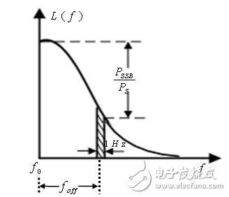
Figure 2 Schematic diagram of SSB phase noise
3 Design requirementsMain electrical characteristics of the designed 2856MHz microwave source:
Output signal frequency: 2856MHz;
Signal output power:
1-port, 2-port output power ≥100mW (20dBm),
3-port, 4-port output power ≥ 20mW (13dBm);
Output signal frequency accuracy: ≤ ± 50KHz;
Output signal phase noise: ≤ -105dBc / Hz @ 20KHz;
Harmonic clutter suppression: ≥50dBc;
Amplifier bandwidth: ≥ 4MHz;
Inter-channel isolation: ≥40dBc.
4 design planAccording to the design requirements, after a variety of scheme comparisons, the solution of the phase-locked dielectric oscillator circuit is finally adopted. Its composition is mainly composed of reference source, PDRO (phase-locked dielectric oscillator), 1:4 power amplifier amplification and power supply, as shown in Figure 3. The working principle, the 102MHz signal generated by the reference source and the microwave signal sampled by the dielectric oscillator in the PDRO are phase-locked to lock the PDRO output signal at 2856MHz. The signal output by PDRO is amplified by a 1:4 power split.
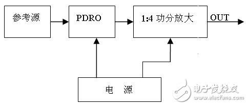
Figure 3 circuit block diagram
4.1 Dielectric Oscillator
The dielectric oscillator is a resonator made of a low-loss, high-k dielectric material. The medium is coupled to the microstrip line to form a high-Q resonant circuit with sharp frequency selection characteristics. At the same time, the bandwidth of the dielectric oscillator is very narrow (designed to be 0.3%~0.5%). In the voltage control range, only one frequency point is an integral multiple of the reference source frequency, and the dielectric oscillator can only be locked at the designed frequency point. Therefore, the phase noise of the dielectric oscillator is superior to other forms of oscillator. The dielectric oscillator has the advantages of small volume, high Q value, large frequency range (up to millimeter band), good frequency stability at high and low temperatures, and the like, and is widely used in microwave circuits. The principle of PDRO (Phase Locked Media Oscillator) is shown in Figure 4.
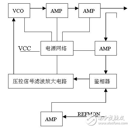
Figure 4 PDRO schematic
AMP (microwave amplification unit), VCC (+12 power supply), REFMON (reference frequency)
4.2 Pulse frequency doubling phase-locked loop circuit
The working principle of the pulse multiplying phase-locked loop circuit is shown in Fig. 5. The working process is that the 102MHz reference source passes through the pulse forming circuit to generate a sharp pulse sequence of 102MHz integer multiple harmonics. In the phase detector, the VCO frequency is 2856MHz and the 28th harmonic of 102MHz is phased. The phase of the VCO is locked to 2856MHz through the phase-locked loop. Compared with the frequency doubling chain technology, the pulse frequency PLL adopts a sampling phase detector to sample the high frequency signal outputted by the VCO at the sampling pulse peak, and the obtained control signal filters the high frequency through the loop filter. After the component, the output signal of the VCO is controlled by the operational amplifier to amplify the output DC signal, so that the VCO output frequency is directly locked to the higher harmonic of the reference frequency. Compared with the digital frequency division lock-in technology, the influence of the digital frequency division noise base is eliminated, and the phase noise is obviously superior to the digital frequency division phase lock, and the phase noise is close to the theoretical value.
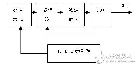
Figure 5 How the pulse multiplier phase-locked loop circuit works
5 Phase noise actual measurement and analysisSmart Watches
Smart Watches
everyone enjoys luck , https://www.eeluck.com
