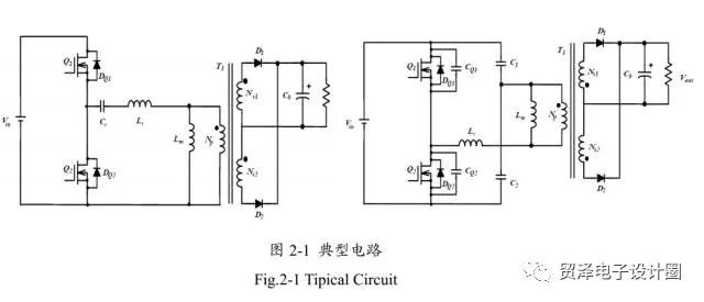
In the LLC half-bridge resonant circuit, the typical LLC resonant circuit has two connections according to the different coupling modes of the resonant capacitor, as shown in Figure 1 below. The difference lies in the connection of the LLC resonant cavity. The left figure uses a single resonant capacitor (Cr). The input current ripple and current have higher RMS values, but the wiring is simple and the cost is relatively low. The right figure uses a split resonant capacitor (C1). , C2), its input current ripple and current RMS are low, only half of the rms current flows through C1 and C2, and the capacitance is only half of the single resonant capacitor on the left.
The DC characteristics of the LLC resonant conversion are divided into a zero voltage working area and a zero current working area. This transformation has two resonant frequencies. One is the resonance point of Lr and Cr, and the other resonance point is determined by Lm, Cr and load conditions. As the load increases, the resonant frequency will increase. The calculation formulas of these two resonance points are as follows:
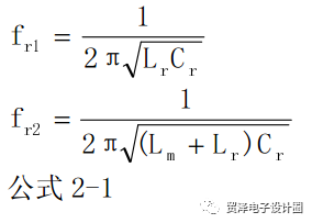
In order to maximize efficiency, the operating frequency must be set near fr1 when designing the circuit. Where fr1 is the resonant frequency of the Cr, Lr series resonant cavity. When the input voltage drops, a larger gain can be obtained by lowering the operating frequency. By selecting the appropriate resonant parameters, the LLC resonant converter can operate in a zero voltage operating region regardless of load variation or input voltage variation.
In general, the switching action of the LLC half-bridge resonant circuit is the same as that of the half-bridge circuit. However, due to the addition of the resonant cavity, the upper and lower MOSFETs in the LLC half-bridge resonant circuit operate differently, which enables the MOSFET to be turned on at zero voltage. Its working waveform is as follows:
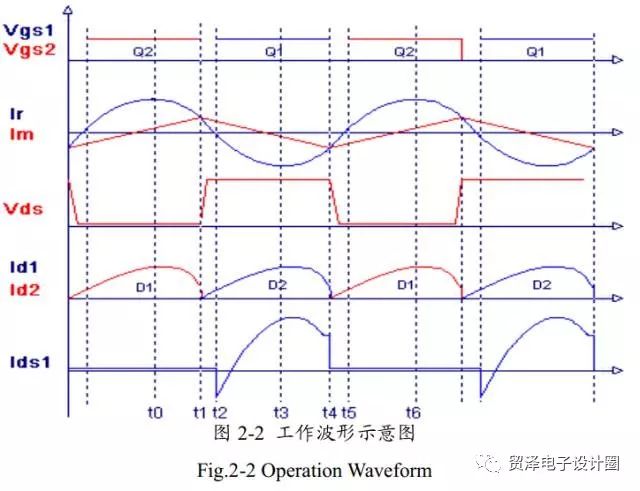
The figure above shows the working waveform of the ideal half-bridge resonant circuit. In the figure, Vgs1 and Vgs2 are the driving waveforms of Q1 and Q2, Ir is the resonant inductor Lr inductor current waveform, and Im is the transformer leakage inductance Lm current waveform. Id1 and Id2 are respectively The secondary side outputs the rectified diode waveform, and Ids1 is the Q1 on current. The waveform diagram is divided into 6 stages according to different working states. The following is a detailed analysis of each state, and the LLC resonant circuit works:
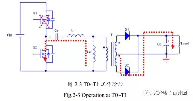
T0~ T1
Q1 is turned off and Q2 is turned on; at this time, the current on the resonant inductor is negative, and the direction flows to Q2. At this stage, the leakage inductance of the transformer does not participate in the resonance, Cr and Lr constitute the resonant frequency, and the output energy comes from Cr and Lr. This phase ends with Q2 turned off. Figure 3 below shows the working state of each component of the LLC half-bridge resonant circuit during the T0~T1 working phase.
T1~ T2
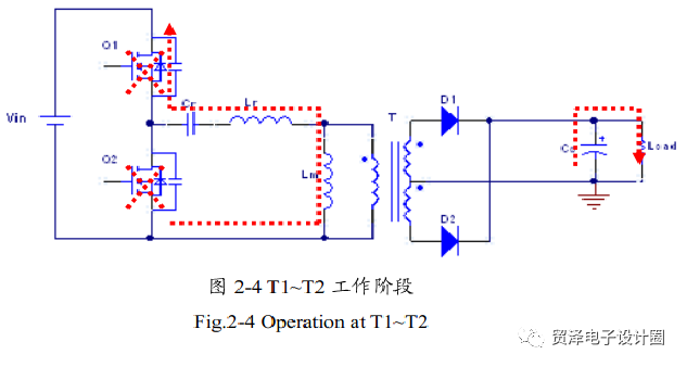
Q1 is turned off and Q2 is turned off; at this time, the dead time of the half bridge circuit, the current on the resonant inductor is still negative, the resonant current discharges the output capacitance (Coss) of Q1, and the output capacitance (Coss) of Q2 is performed. Charging until the voltage of the output capacitor of Q2 is equal to the input voltage (Vin), which creates a zero voltage turn-on condition for Q1 next time. Since the Q1 body diode is forward biased, and the body diode of Q2 shows an inverting bias, the currents on the two inductors are equal. The output voltage is higher than the secondary side voltage of the transformer, and D1 and D2 are in a reverse bias state, so the output terminal is separated from the transformer. At this stage, Lm and Lr, Cr participate in resonance together. As Q1 opens, the T1~T2 phase ends. Figure 4 below shows the working state of each component in the working phase of the LLC half-bridge resonant circuit from T1 to T2.
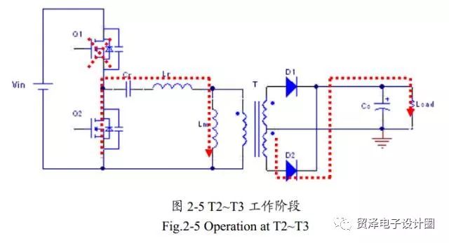
T2~ T3
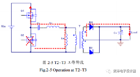
Q1 is turned on and Q2 is turned off (once the output capacitor of Q1 is discharged to zero). At this point, the current on the resonant inductor is still negative, and the current flows back to the input terminal (Vin) through the body diode of Q1. At the same time, the output rectifier diode (D1) is turned on to provide energy to the output. The transformer leakage inductance (Lm) is continuously charged at this stage. Only Lr and Cr participate in resonance. Once the current on the resonant inductor Lr is zero, the T2~T3 phase ends. Figure 5 below shows the working conditions of the components of the LLC half-bridge resonant circuit during the T2~T3 working phase.
T3~ T4
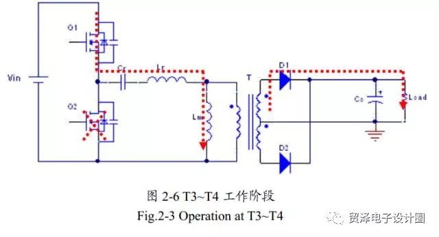
This phase begins with the resonant inductor Lr current becoming negative and positive, Q1 turned on, and Q2 turned off, the same as the T2~T3 phase. The resonant inductor current begins to flow from input to Q1 via Q1. The transformer leakage inductance Lm is now charged by this current, so the devices participating in the resonance are only Lr and Cr. The output is still transmitting energy by D1. As Q1 turns off, the T3~T4 phase ends. Figure 2-6 below shows the working status of each component in the working phase of the LLC half-bridge resonant circuit during T3~T4.
T4~ T5
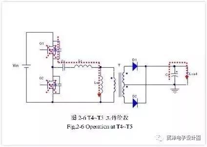
Q1 is turned off and Q2 is turned off; this is the half-bridge circuit dead time. At this time, the resonant inductor current charges the output capacitor Coss of Q1, and discharges the output capacitor Coss of Q2 until the output capacitor voltage of Q2 is zero, turning on the body diode of Q2 to create conditions for Q2 zero voltage turn-on. During this period, the secondary side of the transformer is separated from the primary side as in the T1~T2 phase. At the time of death, the transformer leakage inductance Lm participates in the resonance. This phase ends with the opening of Q2. Figure 7 below shows the working status of each component in the working phase of the LLC half-bridge resonant circuit during T4~T5.
T5~ T6
Q1 is turned off and Q2 is turned on. Since the output capacitance of Q2 has been discharged to zero in the T4~T5 phase, Q2 is turned on at zero voltage in the T5~T6 phase. The energy is freewheeled by the resonant inductor Lr via Q2, and the output is powered by D2. At this time, Lm does not participate in the resonance of Lr and Cr. At this stage, the end of the resonant inductor Lr becomes zero, and the T0 to T1 state is repeated. Figure 8 below shows the working state of each component of the LLC half-bridge resonant circuit during the working phase of T5~T6.
It can be seen from the above working states that, except for the dead time of Q1 and Q2, the circuit can work at a higher resonant frequency composed of Lr and Cr most of the time. In this case, the leakage inductance of the transformer is clamped by the output voltage, so it exists as a load form of the Lr, Cr series resonator, and does not participate in the entire resonance process. Due to this passive load, LLC resonant conversion light load regulation can no longer require very high frequencies. Moreover, due to this passive Lm load, it is guaranteed to operate in a zero voltage switching state under any load conditions.
The multi-speed air supply mode can bring you a comfortable and cool breeze in various scenarios. The 180° wide-angle surrounds the healthy and refreshing natural wind, and the soft wind blows on the face, returning to the natural and refreshing. The fuselage is equipped with a lanyard, so you can take the wind with you anytime anywhere.
Neck Fan,Small Fan,Portable Mini Fan,Hanging Neck Fan
Dongguan Yuhua Electronic Plastic Technology Co.,Ltd , https://www.yuhuaportablefan.com
