Accelerometers measure acceleration, tilt, vibration or shock and are therefore suitable for a wide range of applications from wearable fitness devices to industrial platform stabilization systems. There are hundreds of accelerometer devices on the market to choose from, with varying costs and performance.
The latest MEMS capacitive accelerometers are used in applications traditionally dominated by piezoelectric accelerometers and other sensors. The new generation of MEMS accelerometers provides solutions for applications such as CBM, Structural Health Monitoring (SHM), Asset Health Monitoring (AHM), Vital Signs Monitoring (VSM) and IoT Wireless Sensor Networks. However, with so many accelerometers and so many applications, choosing the right accelerometer is not easy.
There are no industry standards that define which category an accelerometer belongs to. The general classification of accelerometers and their corresponding applications are shown in Table 1. The illustrated range of bandwidth and g values ​​is typical of accelerometers used in the listed end applications.
Table 1. Accelerometer ratings and typical application areas
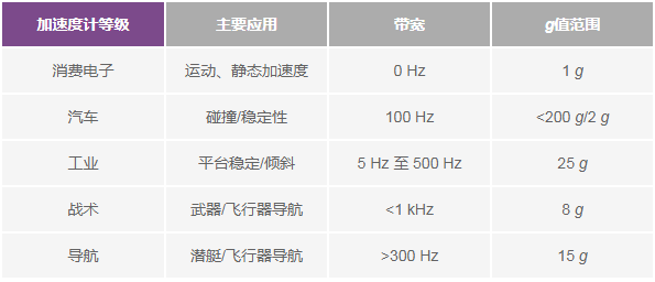
Figure 1 shows a snapshot of various MEMS accelerometers, categorizing each sensor based on the main performance metrics and intelligence/integration levels of the particular application. An important focus of this paper is a new generation of accelerometers based on enhanced MEMS structures and signal processing, as well as world-class packaging technology, which offers comparable stability and noise performance to more expensive specialized devices with lower power consumption. These characteristics and other key specifications of the accelerometer will be discussed in detail below based on application relevance.
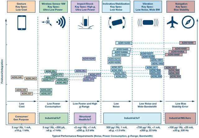
Figure 1. Application map of ADI's selected MEMS accelerometer
Tilt detectionMain criteria: bias stability, offset drift, low noise, repeatability, vibration correction, cross-axis sensitivity.
For MEMS capacitive accelerometers, accurate tilt detection is a demanding application, especially in the presence of vibration. It is very difficult to achieve a tilt accuracy of 0.1° using a MEMS capacitive accelerometer in a dynamic environment—<1° is difficult, and >1° is easier to implement. In order for the accelerometer to effectively measure the tilt, a good understanding of the sensor performance and the end application environment is required. Compared to dynamic environments, static environments are more advantageous for tilt measurements because vibration or shock can corrupt the tilt data and cause serious measurement errors. The most important characteristics of tilt measurement are temperature coefficient offset, hysteresis, low noise, short/long term stability, repeatability and good vibration correction.
0 g offset accuracy, 0 g offset drift due to soldering, 0 g offset drift due to PCB housing alignment, 0 g bias temperature coefficient, sensitivity and temperature coefficient, nonlinearity, and cross-axis sensitivity , is observable and can be reduced by the post-assembly calibration process. Hysteresis, 0 g offset drift during lifetime, sensitivity drift during lifetime, 0 g drift due to humidity, and PCB bending and torsion caused by temperature changes over time, etc. These error terms cannot be resolved by calibration or other methods It needs to be reduced by a certain degree of in-situ maintenance.
Analog Devices' accelerometers are available in MEMS (ADXLxxx) and iSensor® (ADIS16xxx) special-purpose devices. iSensor or Smart Sensors are highly integrated (4 to 10 degrees of freedom) programmable devices for complex applications in dynamic environments. These highly integrated plug-and-play solutions include comprehensive factory calibration, embedded compensation, and signal processing that address many of the above-mentioned in-situ repair errors, greatly reducing design and verification burden. This comprehensive factory calibration provides sensitivity and bias characteristics over the entire sensor signal chain over the specified temperature range (typically −40°C to +85°C). Therefore, each iSensor device has its own unique compensation formula that produces accurate measurements when installed. For some systems, factory calibration eliminates system-level calibration and greatly simplifies operation.
iSensor devices are specifically developed for certain applications. For example, the ADIS16210 shown in Figure 2 is specifically designed and customized for tilting applications, so it provides a relative accuracy of <1° and is ready to use right out of the box. This is mainly due to integrated signal processing and specific device calibration for optimum accuracy performance. The iSensor device will be discussed further in the Stability section.
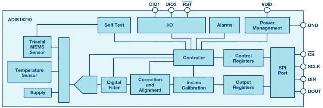
Figure 2. ADIS16210 Precision Triaxial Tilt
The latest generation of accelerometer architectures (such as the ADXL355) offer more features (tilt, status monitoring, structural health, IMU/AHRS applications), and include integrated modules that are less specific to the application but feature-rich, as shown in Figure 3.
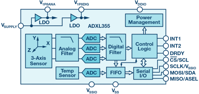
Figure 3. Low noise, low drift, low power 3-axis MEMS accelerometer ADXL355
The following is a comparison of the ADXL345 general-purpose accelerometer and the ADXL355, a new generation of low-noise, low-drift, low-power accelerometers, which are ideal for a wide range of applications, such as IoT sensor nodes and inclinometers. This comparison looks at the sources of error in tilting applications and the errors that can be compensated or eliminated.
Table 2 lists the expected performance specifications for the consumer grade ADXL345 accelerometer and estimates of the corresponding tilt error. Some form of temperature stabilization or compensation must be used when attempting to achieve optimum tilt accuracy. In the example below, the constant temperature is assumed to be 25 °C. The main causes of error that cannot be fully compensated are temperature drift offset, offset drift, and noise. Bandwidth can be reduced to reduce noise because tilted applications typically require bandwidths below 1 kHz.
Table 2. ADXL345 Error Source Estimates
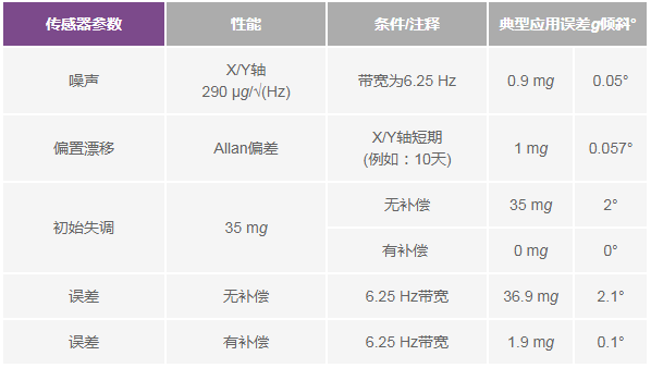
Table 3 lists the same standards that apply to the ADXL355. The short-term bias values ​​are estimated from the Allan variance plot in the ADXL355 data sheet. At 25 ° C, the estimated tilt accuracy of the universal ADXL345 after compensation is 0.1 °. The industrial grade ADXL355 has an estimated tilt accuracy of 0.005°.
Table 3. ADXL355 Error Source Estimates
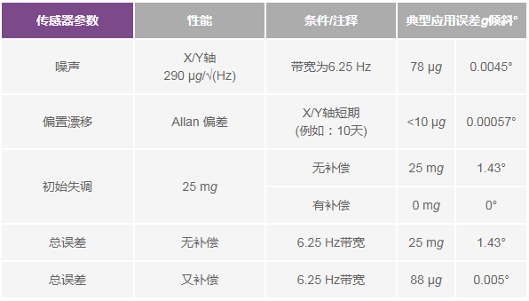
By comparing the ADXL345 and the ADXL355, it can be seen that the error caused by the significant error contribution factor has been significantly reduced. For example, the noise-induced error is reduced from 0.05° to 0.0045°, and the error caused by the offset drift is reduced from 0.057° to 0.00057°. This shows that MEMS capacitive accelerometers have made a huge leap in performance such as noise and offset drift, providing higher levels of tilt accuracy under dynamic conditions.
Choosing a higher level accelerometer is critical to achieving the desired performance, especially if the application requires a tilt accuracy of less than 1°. Application accuracy depends on application conditions (temperature fluctuations, vibration) and sensor selection (consumer and industrial or tactical). In this case, the ADXL345 will require a large amount of compensation and calibration to achieve tilt accuracy of less than 1°, increasing the overall system effort and cost. Depending on the magnitude of the vibration in the final environment and temperature range, it is even impossible to achieve the above accuracy. The temperature coefficient offset drift in the range of 25 ° C to 85 ° C is 1.375 °, which exceeds the requirement that the tilt accuracy is less than 1 °.

The maximum temperature coefficient offset drift of the ADXL355 is 0.5° from 25°C to 85°C.

The repeatability of ADXL354 and ADXL355 (±3.5 mg/0.2° for the X and Y axes and ±9 mg/0.5° for the Z axis) is a 10-year life expectancy including high temperature working life test (HTOL) (TA = 150 °C) , VSUPPLY = 3.6 V, 1000 hours), temperature cycle (−55 ° C to +125 ° C and 1000 cycles), random walk, speed of broadband noise and temperature hysteresis. These new accelerometers provide repeatable tilt measurements under all conditions, eliminating the need for extensive calibration in harsh environments to achieve minimum tilt errors and minimizing post-deployment calibration needs. The ADXL354 and ADXL355 accelerometers guarantee temperature stability with a zero offset factor of 0.15 mg/°C (max). This stability minimizes the resources and cost associated with calibration and testing, helping equipment OEMs achieve higher throughput rates. In addition, the product is packaged in a sealed package to ensure that the repeatability and stability of the final product consistent with its specifications.
In general, repeatability and suppression of vibration correction errors (VRE) are not shown in the data sheet as these parameters may expose product performance to a lower level. For example, the ADXL345 is a universal accelerometer for consumer applications, and VRE is not an important concern for designers. However, in certain environments where high-demand applications such as inertial navigation, tilting applications, or vibrations are frequent, the ability to suppress VRE may be a key concern for designers, so the ADXL354/ADXL355 and ADXL356/ADXL357 data sheets will give such parameters. .
As shown in Table 4, VRE is the offset error introduced when the accelerometer is exposed to broadband vibration. When the accelerometer is exposed to a vibrating environment, the VRE causes significant errors in the tilt measurement compared to the 0 g offset caused by temperature drift and noise. This is one of the main reasons why the data sheet is no longer used, as it is easy to cover other major specifications.
Table 4. Errors expressed in terms of slope

(1. The range of 1g azimuth misalignment caused by 2.5g rms vibration is ±2g.)
VRE is the response of an accelerometer to AC vibration (converted to DC). These DC rectified vibrations can skew the accelerometer offset, causing serious errors, especially in tilted applications where the target signal is a DC output. Any small change in dc offset can be interpreted as a change in tilt, resulting in system level errors.
Filters in various resonant and accelerometers (in this case, the ADXL355) can cause VRE because VRE has a strong dependence on frequency. These resonances amplify the vibration, the amplification factor is equal to the Q factor of the resonance, and the vibration is suppressed at higher frequencies because the resonator has a second-order dipole response. The higher the resonance quality factor of the sensor, the larger the vibration amplitude and the larger the VRE. A larger measurement bandwidth will include vibrations in the high frequency band, resulting in a higher VRE, as shown in Figure 4. Choosing the right bandwidth for the accelerometer to suppress high frequency vibrations can avoid many vibration related problems.
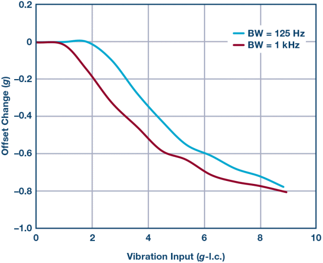
Figure 4. ADXL355 VRE test at different bandwidths
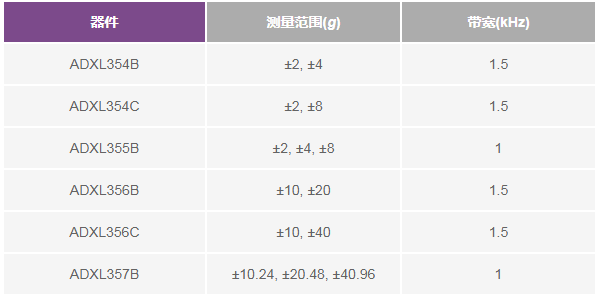
Static tilt measurements typically require a low g accelerometer of ±1g to ±2g with a bandwidth of less than 1.5 kHz. Analog output ADXL354 and digital output ADXL355 are low noise density (20 μg √Hz and 25 μg √Hz, respectively), low 0g offset drift, low power triaxial accelerometer, integrated temperature sensor, measurement range optional, as shown 5 is shown.
Table 5. ADXL354/ADXL355/ADXL356/ADXL357 Measurement Range
The ADXL354/ADXL355 and ADXL356/ADXL357 are packaged in a hermetic package for excellent long-term stability. Performance improvement is usually positively related to the package, as shown in Figure 5. Packaging is often overlooked, and manufacturers can use packages to achieve better stability and drift performance. This is a key focus for ADI, and we offer a wide range of sensor packages to suit different applications.
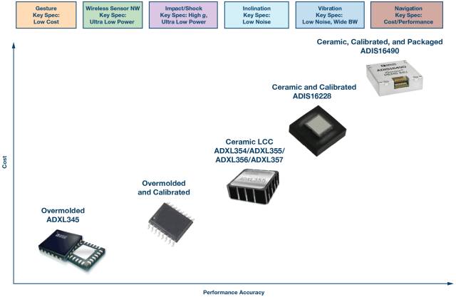
Figure 5. Example of performance improvements with advanced packaging techniques and calibration
High temperature and dynamic environmentSome designers have had to use standard temperature ICs far beyond the limits of the data sheet before accelerometers suitable for high temperatures or harsh environments are available. This means that the end user is responsible for the responsibility and risk of verifying the quality of the device at high temperatures, which is costly and time consuming. It is a well-known fact that sealed packages can withstand high temperatures, preventing corrosion through a barrier against moisture and pollution. Analog Devices offers a wide range of sealing devices with enhanced temperature stability and performance. ADI has also been researching the performance of plastic packages at high temperatures, especially the ability of leadframes and leads to accommodate high temperature soldering processes, making them robust and reliable in high shock and vibration environments. As a result, Analog Devices offers 18 accelerometers rated for −40°C to +125°C, including the ADXL206, ADXL354/ADXL355/ADXL356/ADXL357, ADXL1001/ADXL1002, ADIS16227/ADIS16228, and ADIS16209. Most competitors do not offer MEMS capacitive accelerometers that operate over the temperature range of −40°C to +125°C or under harsh environmental conditions such as heavy industrial machinery and downhole drilling.
Tilt measurement in harsh environments with temperatures above 125 °C is a challenging task. The ADXL206 is a high precision (tilt accuracy <0.06°), low power, complete dual axis MEMS accelerometer for high temperature and harsh environments such as downhole drilling. The device is available in a 13 mm × 8 mm × 2 mm side brazed, ceramic, dual in-line package that supports an ambient temperature range of −40°C to +175°C. Performance drops below 175°C, but 100 % can be recovered.
Tilt measurements in dynamic environments with vibrations (such as agricultural equipment or drones) require accelerometers with a high range of g values, such as the ADXL356/ADXL357. Accelerometer measurements in the finite g range may clip, resulting in an increase in output offset. The cause of the clipping may be that the sensitive axis is in the 1 g gravitational field, or the impact of a fast rise time but a slow decay. A higher g-value range reduces accelerometer clipping, which reduces offset and provides better tilt accuracy in dynamic applications.
Figure 6 shows a measurement with a limited range of g values ​​for the ADXL356 Z-axis, where 1g already exists.
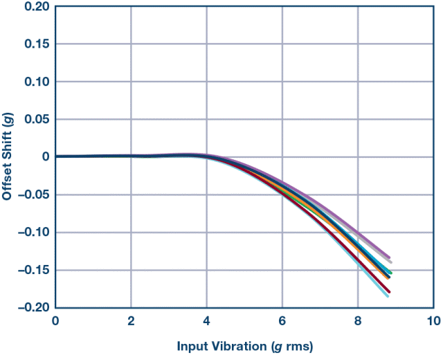
Figure 6. ADXL356 VRE, Z-axis offset versus 1 g, ±10 g range, Z-axis direction = 1 g
Figure 7 shows the same measurement, but the g value range extends from ±10 g to ±40 g. It can be clearly seen that the g-scale extension of the accelerometer significantly reduces the offset caused by clipping.
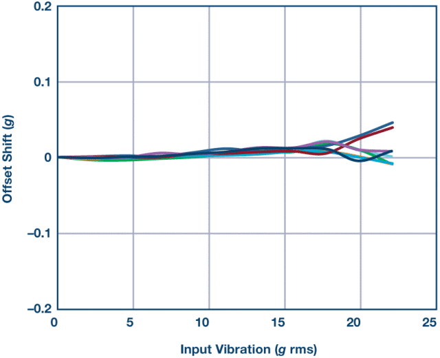
Figure 7. ADXL356 VRE, Z-axis offset relative to 1 g, ±40 g range, Z-axis direction = 1 g
The ADXL354/ADXL355 and ADXL356/ADXL357 offer excellent vibration correction, long-term repeatability, and low noise performance, and are small in size, making them ideal for tilt detection applications in both static and dynamic environments.
stableMain criteria: noise density, random walk at speed, bias stability during motion, offset repeatability, and bandwidth.
Detecting and understanding motion can benefit many applications. It is beneficial to take control of a system's movements and then use this information to improve performance (short response time, increase accuracy, speed up), enhance safety or reliability (system shut down in hazardous situations), or gain other value-added features. of. Due to the complexity of motion, there are a large number of stability applications that require the use of gyroscopes and accelerometers (sensor fusion, as shown in Figure 8), such as UAV monitoring equipment and onboard antenna pointing systems.
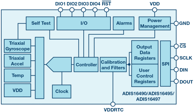
Figure 8. 6 degrees of freedom IMU
The 6 degrees of freedom IMU uses multiple sensors to compensate for each other's weaknesses. It may seem like a simple inertial motion on one or two axes, which may actually require the fusion of an accelerometer and a gyro sensor to eliminate vibration, gravity, and other influencing factors that cannot be accurately measured by accelerometers or gyroscopes alone. Accelerometer data includes gravity components and motion acceleration. The two cannot be distinguished, but the gyroscope can be used to remove the gravity component from the accelerometer output. In order to determine the position based on the acceleration, integration is required, and after this process, the error caused by the gravity component of the accelerometer data may rapidly become large. Due to the cumulative error, the gyroscope alone is not sufficient to determine the position. The gyroscope does not detect gravity and can therefore be used as an auxiliary sensor for accelerometers.
In stability applications, MEMS sensors must accurately measure the orientation of the platform, especially during motion. Figure 9 is a block diagram of a typical platform stabilization system that uses servo motors to correct angular motion. The feedback/servo motor controller converts the direction sensor data into a servo motor correction control signal.
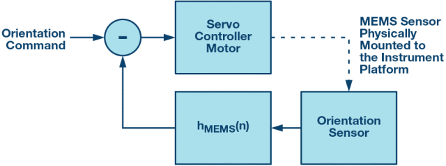
Figure 9. Basic platform stabilization system
The final application will determine the level of accuracy required, and the quality of the selected sensor (consumer or industrial) will determine if it can be achieved. It is important to distinguish between consumer and industrial devices. Sometimes the difference between the two is subtle and may require careful consideration. Table 6 shows the main differences between consumer-grade accelerometers and mid-range industrial accelerometers integrated in the IMU.
Table 6. Industrial MEMS devices comprehensively measure all known potential sources of error with an accuracy level that is more than an order of magnitude higher than that of consumer devices
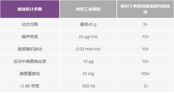
Performance requirements can be met with low precision devices where certain conditions are favorable and less accurate data can be accepted. However, the demand for sensors capable of operating in a dynamic environment is rapidly increasing, and lower precision devices are greatly affected by the inability to reduce vibration effects or temperature effects in actual measurements, and it is difficult to achieve pointing accuracy of less than 3° to 5°. Most low-end consumer devices do not provide parameter specifications such as vibration correction, angular random walk, and these specifications are probably the largest source of error in industrial applications.
In order to achieve 1° or even 0.1° pointing accuracy in a dynamic environment, the designer's device selection must focus on the sensor's ability to suppress temperature drift errors and vibration effects. Sensor filtering and algorithms (sensor fusion), while a key element in improving performance, do not eliminate the gap between consumer and industrial sensors. The performance of ADI's new industrial IMU is close to that of the previous generation of missile guidance systems. Devices such as the ADIS1646x and the announced ADIS1647x ​​offer precision motion detection in standard and mini-IMU form factors, breaking into special applications in the past.
Washing Machine Motor,Spin Motor Of Aluminium Wire,Washing Machine Motor Shaft,Automatic Washing Machine Spin Motor
WUJIANG JINLONG ELECTRIC APPLIANCE CO., LTD , https://www.jinlongmotor.com
