
Aiming at the difficulty of detecting the micro-variable capacitance of the capacitive sensor, a digital universal detection interface scheme is proposed. The principle of direct micro-capacitance measurement based on "excitation-detection" is analyzed. The carrier is generated by DDS, and the amplitude and phase of the measurement result are separated by discrete Fourier transform to obtain the capacitance change. According to the measurement needs of the proximity capacitive sensor, a specific hardware circuit is designed for verification. The experimental results show that the detection accuracy is above 95%. The interface scheme can detect the micro-variable capacitance with the design value above 0.1pF. The design is simple and has strong portability.
1 Introduction
Capacitive sensors have the advantages of small size, low power consumption, high sensitivity, etc., and are widely used in various non-electrical measurements such as acceleration, angular velocity, and pressure. However, unlike pure resistive sensors, the capacitive sensor's detection interface is difficult and complex to design. It is usually amplified and sampled using analog discrete components, which not only increases the system size, but also introduces additional temperature and nonlinearity. error. In this paper, a universal capacitive sensor digital detection interface is proposed. By comprehensively analyzing the relationship between amplitude and phase, the design is simplified, the error is reduced, and the detection accuracy is improved.
2 capacitive sensor model
Capacitive sensor is a device that converts the non-electricity to be measured into a change in capacitance. It can be widely used in the measurement of acceleration, angular velocity, pressure and other parameters. In order to increase the signal amount, the variable pitch method is often used for sensitivity.
Taking a capacitive pressure sensor as an example, its simplified basic structure is shown in Figure 1. A1 and A2 are two capacitor plates, of which A1 is a fixed plate, A2 is a movable plate, and A3 is a sensitive diaphragm for sensing the change of the air pressure to be measured, and d is the distance between A1 and A2. When there is an external input to be measured, A3 will push A2 to move to A1, thus changing the capacitance between the plates of A1 and A2. As long as the change of the capacitance is detected, the corresponding air pressure value can be converted.
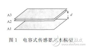
When there is no air pressure input, the initial capacitance of the sensor is:

Where: ε is the dielectric constant, A is the relative area between the plates, and d0 is the initial spacing between the plates.
When there is external air pressure input, as A2 moves to A1, d0 decreases. At this time, the capacitance of the sensor is:
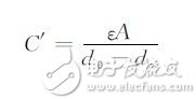
Where: dx is the amount of change in spacing.
3 Direct interface detection principle
Common capacitive sensor interfaces include continuous-time readout (such as charge amplifier type and transimpedance amplifier type) and discrete-time readout (such as switched capacitor type), which change the capacitance to be measured into voltage or current. Detection is essentially an indirect detection method that is not conducive to System Integration. As a kind of non-pure resistive component, the capacitor modulates the amplitude and phase of its own electrical signal. With this relationship, a capacitive interface scheme that simultaneously detects amplitude and phase can be designed.
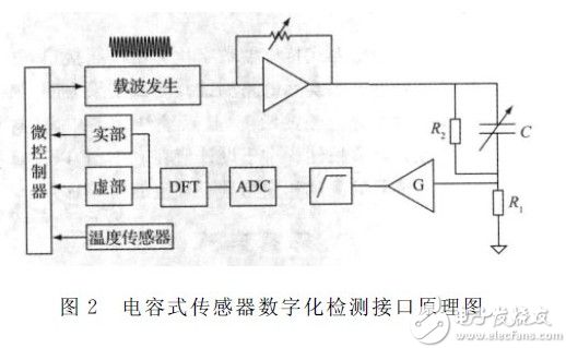
Figure 2 shows the interface design, C is a capacitive sensor, R1 and R2 are auxiliary resistors, which are selected and matched according to the capacitance of the sensor to be tested.
The microcontroller uses the DDS method to send a single-frequency sinusoidal carrier. After amplitude adjustment, it is sent to the capacitive sensor. After comparison with the auxiliary resistor, the waveform is amplified and filtered, and the obtained value is discretely Fourier transformed to separate the real part. After the imaginary part is sent back to the microcontroller for subsequent calculation and linearization.
Assuming the carrier VDDS = A0sin(2Ï€ft), the amplitude-shaped sensor excitation voltage is  (A1 is the amplification factor), the detection voltage is:
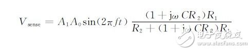
Separating the detection voltage after AD conversion can solve the corresponding capacitance complex impedance as:
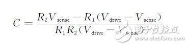
Where: Vdrive and Vsense are complex variables.
Since the input signal is a sinusoidal signal and has periodicity, the amplitude and phase information of the signal are stored in the real part and the imaginary part, respectively, and the DFT of the Vsense can obtain the change information of the capacitance to be tested.
4 detection interface actual circuit design
Due to the variety of capacitive sensors and the wide range of capacitance values, it is necessary to select suitable devices according to different measurement ranges to achieve the above measurement principle. The capacitive proximity sensor is a widely used capacitive sensor with a total of three plates. One part of the human body to be tested (such as a finger) is a movable plate, and two pieces are fixed plates. One block is excited with a constant sinusoidal voltage; the other block is grounded. When the human body approaches, the capacitance becomes large, and when a certain threshold is exceeded, the human body is considered to be close. The core of the whole sensor lies in the detection of micro-variable capacitance. Based on the above principle, the actual circuit is designed.
Lithium Ion Battery,5G Integrated Battery,Custom Ups Lithium Ion Battery,Communication Ladder Backup Battery
Wolong Electric Group Zhejiang Dengta Power Source Co.,Ltd , https://www.wldtbattery.com