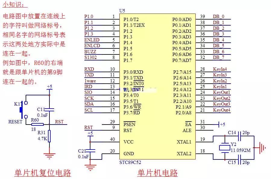
The minimum system of a single-chip microcomputer, also called the minimum application system of a single-chip microcomputer, refers to a system in which a single-chip microcomputer can work with a minimum of original components. The three elements of the MCU minimum system are the power supply, crystal oscillator, and reset circuit, as shown in Figure 2-1.

Figure 2-1 Minimum system circuit of the microcontroller
The circuit diagram of this minimum system is selected from our KST-51 development board schematic. Below we will analyze the three elements of the minimum system according to this circuit diagram.
1) The power supply is well understood. Electronic devices need to be powered. Even our household appliances (flashlight ^_^) are no exception. At present, the power supply of mainstream MCUs is divided into two standards of 5V and 3.3V. Of course, there are still single-chip microcomputer systems with lower voltage requirements, which are generally used in some specific occasions. We do not pay much attention in learning.
We chose the STC89C52, which requires a 5V power supply system. Our development board is powered directly from 5V DC output from the USB port. As can be seen from Figure 2-1, the power supply circuit is at the 40-pin and 20-pin positions. The 40-pin is connected to +5V, which is also commonly referred to as VCC or VDD, which represents the positive power supply and the 20-pin is GND. Represents the negative pole of the power supply. There is also a capacitor between +5V and GND, which will be introduced in the next lesson.
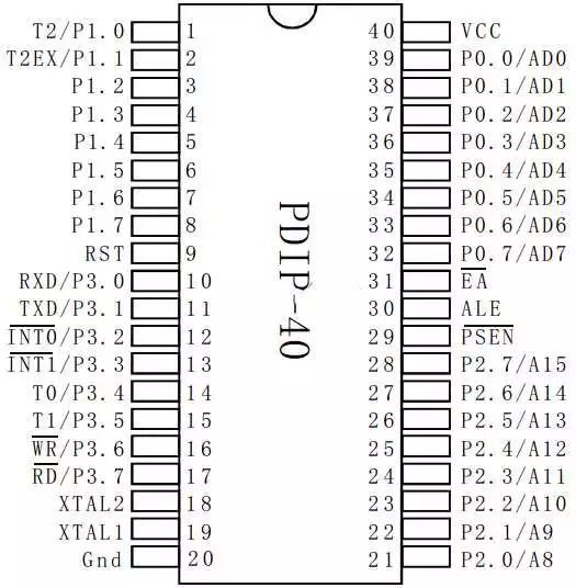
In this place we also need to popularize a knowledge of the schematic. The schematic diagram of the circuit exists to express the working principle of this circuit. Many devices consider the convenience principle analysis when drawing, instead of expressing the actual position of each device. For example, the pin diagram of the MCU in the schematic diagram, the position of the pin can be freely placed, but each pin has a digital label, which is the true pin position of the MCU. Under normal circumstances, this dual in-line package chip, the upper left corner is 1 foot, the counterclockwise rotation of the pin number increases sequentially, until the upper right corner is the maximum pin, we now use a total of 40 pins. Therefore, the upper right corner is 40 (inside the box indicating the chip), as shown in Figure 2-2, you need to distinguish the difference between the schematic pin number and the actual pin position.

Figure 2-2 Package diagram of the microcontroller
2) The crystal oscillator, also known as the crystal oscillator, can be seen from this name. It is destined to oscillate all the time.
His role is to provide a reference clock signal for the MCU system, similar to the person who calls the password during the training of the troops. All the work inside the MCU works with this clock signal as the benchmark. The 18-pin and 19-pin of the STC89C52 MCU are crystal pins. We have connected a crystal of 11.0592M (which oscillates 11,059,200 times per second), plus two 20pF capacitors. The function of the capacitor is to help the crystal start and maintain oscillation. The signal is stable.
3) The reset circuit is a reset circuit on the left side of Figure 2-1. It is connected to the 9-pin RST (Reset) reset pin of the microcontroller. How does this reset circuit work? Let's talk about it later. Now we will focus on resetting the microcontroller. effect. The reset of the MCU is generally three kinds of cases: power-on reset, manual reset, and program automatic reset.
If our MCU program has 100 lines, when it runs to the 50th line, it suddenly loses power. At this time, the area data inside the MCU will be lost, and some area data may not be lost. Then the next time the device is turned on, we hope that the MCU can run normally. Therefore, after power-on, the MCU should perform an internal initialization process. This process can be understood as a power-on reset. The power-on reset ensures that the MCU is fixed from a fixed time. The same state begins to work. This process is consistent with the process of turning on the computer to turn on the computer.
When our program is running, if the program crashes due to unexpected interference, or when the program runs away, we can press a reset button to re-initialize the program and re-run. This process is called manual reset, the most typical It is the restart button of our computer.
When the program crashes or runs away, our MCUs often have an automatic reset mechanism, such as a watchdog, which will be understood later. In this case, if the program loses response for a long time, the microcontroller watchdog module will automatically reset and restart the microcontroller. There are also some cases where our program intentionally restarts resetting the microcontroller.
The power supply, crystal oscillator and reset constitute the three elements of the minimum system of the MCU. That is to say, a single MCU has these three conditions, and we can run the program we downloaded. Others such as LED small lights, digital tubes, LCDs, etc. It is an external device belonging to the microcontroller, that is, a peripheral device. The final function we want to accomplish is to control a variety of peripherals by programming the microcontroller.
We have been in the Lithium Battery industry for many years and always adhere to the full capacity of the product.Sufficient quantity is not false standard,ensure the power stability of lithium battery ,stable endurance. Our 3.2v 50ah LiFePo4 Battery battery have high diacharge, low battery resistance, stable discharge, longer life cycle. We have higher temperature resistance, higher power discharge.
3.2V Battery Cells,Prismatic Phosphate Lithium Batteries,3.2V 50Ah,3.2v lifepo4 battery,3.2V LifePO4 Lithium Battery Pack
Jiangsu Zhitai New Energy Technology Co.,Ltd , https://www.zt-tek.com
