1 Introduction
In the high-frequency switching converter, the application of magnetic components is very extensive, mainly including transformers and inductors: when the transformer is used, it can function as electrical isolation, buck-boost and magnetic coupling to transmit energy; when the inductor is used, To store energy, smoothing and filtering. And its performance has an important impact on the performance of the converter, especially for the efficiency, volume and weight of the entire device. Therefore, the design of magnetic components is an important part of the design of high frequency switching converters.
The design of the magnetic component in the high-frequency switching converter is usually based on the working state of the iron core, and the core material is reasonably selected, and the core and winding parameters of the magnetic component are correctly designed and calculated. However, due to the too many parameters involved in the magnetic components, the working state is not easy to grasp. Therefore, the conventional design method can not fully reflect its actual working conditions and consider the influence of other factors, it is difficult to achieve the required performance indicators and meet the design. Claim.
In view of the importance, necessity and complexity of the design of magnetic components in high-frequency switching converters, the author uses IntuSOFt's "MagneTIcs Designer" software to calculate and design according to the actual working conditions of magnetic components, and obtain better results. This paper first introduces some problems that should be considered and paid attention to in the design of magnetic components. The specific design method and design process are given for the high-frequency transformer in the 600W double-switch forward converter. Finally, the simulation is used to verify.
2. Points to be considered in the design of magnetic components
2.1 Core transient saturation
At the instant of the high-frequency switching converter, due to the double magnetic flux effect, the core of the magnetic component may transiently saturate, resulting in a large inrush current, resulting in damage to the switching device connected to the magnetic component. Therefore, in order to prevent the transient saturation of the iron core, the following methods can be used: one is to reduce the working magnetic induction intensity value, but this will reduce the utilization rate of the iron core; the second is to increase the soft start link, and reduce the power tube guide at startup. Pass the pulse width and then gradually increase the magnetic induction to the steady state value.
2.2 Winding leakage inductance
The leakage inductance of the winding has a large negative effect on the high frequency switching converter, which affects its normal operation. For example, when the power switch is turned off, the leakage energy storage of the winding is released, and a voltage spike is generated on the main switch to increase the voltage stress of the power device. In addition, a switching converter has a plurality of magnetic components, and thus multiple Parasitic inductance, causing severe electromagnetic interference (EMI). In order to reduce the leakage inductance of the winding, the following measures can be taken: first, selecting the appropriate core structure and shape; second, designing the winding to be thin and high, increasing the winding height and reducing the thickness of the winding; third, using the twisted copper wire for the winding Or a wide copper foil to increase the copper factor; the fourth is to use a layered cross-winding method to make the windings tightly coupled.
2.3 Skin effect
When the magnetic component is operated at high frequency, the alternating current will produce a skin effect, that is, the current distribution on the cross section of the wire is not uniform, the internal current density is small, and the current density at the edge portion is large, so that the effective cross-sectional area of ​​the wire is reduced. The resistance increases. In order to reduce the effect of the skin effect, the wire diameter should be no more than twice the penetration depth.
3. High-frequency transformer design in double-tube forward converter
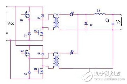
Figure 1 is a schematic circuit diagram of a combined two-switch forward converter, M1, M2, D1, D2 and secondary side topology constitute 1# double-tube forward converter, M3, M4, D3, D4 and secondary side topology constitute 2# Dual tube forward converter. During operation, the control pulse of the 2# converter is phase-shifted by 1800 with respect to the 1# converter. The two-way converter alternates to transmit energy to the secondary side, and the input power is fed back to the primary side through the diodes D1, D2 or D3, D4. Realize the core magnetic reset.

Figure 1 Circuit diagram of a combined dual-switch forward converter
The following is a detailed analysis and design of the high-frequency transformer in Figure 1. The parameters of the circuit are as follows: input voltage VCC = 12v, output voltage Vo = 120v, output current Io = 5A, switching frequency f = 100K, duty cycle D = 0.45, filter inductor Lf = 50 uH.
Easy Electronic Technology Co.,Ltd , https://www.nbpcelectronicgroup.com
