The photonic bandgap (PBG) structure is an artificially constructed periodic dielectric structure. The theory of the photonic bandgap structure comes from the theory of electronic energy bands. The waves propagating in this structure-such as sound waves, electromagnetic waves, Light waves, etc., within a certain frequency range will not be able to propagate in this periodic dielectric structure. This special frequency band is called the band gap. For the design of microstrip antennas, the PBG structure can be used to improve the performance of the antenna, such as increasing antenna gain, enhancing radiation efficiency, and reducing antenna size. But in fact, because the PBG periodic unit size is close to the half-wavelength of the band gap frequency, the PBG structure is limited by its own size in practical applications, especially when applied at lower frequencies.
In this article, we design a novel miniaturized microstrip patch antenna based on a fractal structure, and use the H fractal PBG structure to replace the original ground plane of the microstrip antenna, which greatly reduces the size of the antenna. This new type of miniaturized antenna It will have very good application value for wireless communication systems that require electric small antennas.
2 H fractal PBG structure antenna designFractal topology is a very good mathematical method for analyzing complex problems and chaotic problems. It has a unique self-similar characteristic, which enables fractal topology to form a new structure while keeping the size unchanged. In the application of microwave antenna design and PBG structure, the fractal method is an effective way to realize the miniaturization of the structure, the multiple operating frequencies and the expansion of the frequency bandwidth. The fractal structure used in PBG includes many types, such as H type, Y type, V type and tuning fork type and so on.
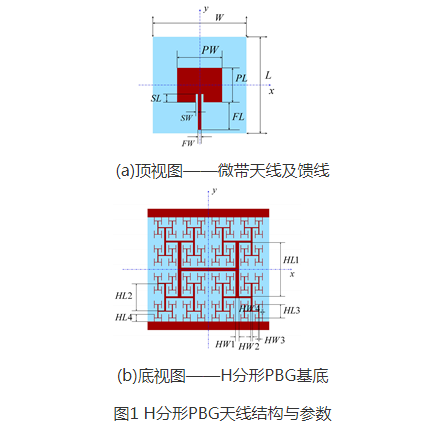
The H-fractal PBG structure is a flat PBG structure, which exhibits multiple band gap characteristics in a very wide frequency range and breaks the traditional relationship between the size of the band gap structure and the band gap frequency. The H fractal structure is constructed with a strip line of length HL and width HW as the first order, and is constructed by repeating the affine transformation of this basic unit. The (k+1)th order structure contains 2k strip lines, and the midpoint of each strip line is connected to the two ends of the kth order strip line. When k is an odd number, the length and width of the (k+1)th order strip line are equal to the kth order, and when k is an even number, the length and width of the (k+1)th order strip line are the kth order strip line Half of it. With the increase of its order, the overall size of the H-fractal PBG structure will be infinitely close to 2(HL+HW)×2(HL+HW).
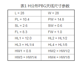
The H fractal PBG antenna includes two metal layers, the dielectric substrate is Rogers RT/Duroid 5880 with h=1mm, and the dielectric constant is εr = 2.2. Figure 1 shows the geometric structure and size parameters of the H fractal PBG antenna. The front side is a traditional patch antenna fed by a microstrip line, and the bottom side uses a 10-order H fractal PBG structure to replace most of the ground plane. The first order is on the x-axis, and the initial design parameters of the structure are shown in Table 1.
The electromagnetic simulation S11 parameters of the H fractal PBG antenna are shown in Fig. 2. The dotted line is the S11 parameters of the traditional substrate microstrip antenna with the same size. It can be seen from the curve in the figure that the working frequency of the traditional microstrip antenna is 8.9GHz, and after adopting the H-fractal PBG structure base, the antenna becomes two radiation frequencies, 2.4GHz and 8.4GHz respectively, this 2.4GHz radiation frequency It is produced by the introduction of the H fractal PBG structure. In the case of the same antenna size, making the antenna work at a lower frequency means a reduction in size. Therefore, the reduction in the size of the H-fractal PBG antenna relative to the size of the traditional microstrip antenna is:
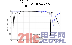
Figure 2 Comparison of H-fractal PBG antenna and traditional antenna S11 parameters. Since the lowest band gap frequency of H-fractal PBG structure depends on the order of fractal and the length of the first-order strip line, these two parameters have an effect on the working frequency of H-fractal PBG antenna. important influence. Figures 3 and 4 respectively show the H-fractal PBG antenna S11 parameters under different HL1 and different orders. It can be seen from the figure that the larger HL1 means that the H-fractal PBG antenna has a lower operating frequency; and the larger the order, the lower the operating frequency, but the 10th-order fractal structure is more matched than the 8th-order and 12th-order structures. The higher is better, so the 10-level structure is the best choice.
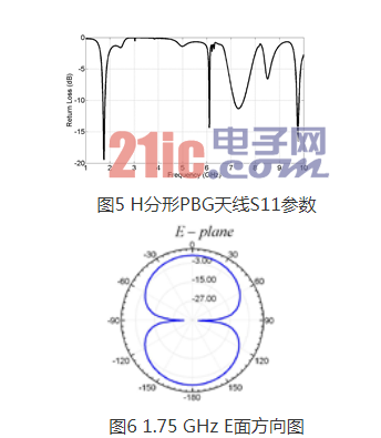
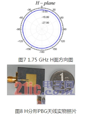
After simulation and optimization, the size of the H-fractal PBG antenna is determined to be HL1=16mm, L=W=36mm, FL=12.3mm, 10th-order fractal structure, and the remaining size parameters are the same as in Table 1. Figure 5 shows the S11 parameters of the H fractal PBG antenna. It can be seen that it has multiple operating frequencies, with a minimum of 1.75GHz, so its size reduction has reached 80.3% compared to the traditional microstrip antenna. Figures 6 and 7 are the directional patterns of the H-fractal PBG antenna at 1.75GHz. At this frequency, the antenna has an omnidirectional radiation characteristic similar to that of a dipole antenna, and the antenna gain is 2.6dB. Figure 8 is a physical photo of the H fractal PBG antenna.
This paper describes the design and optimization of a microstrip patch antenna using the H-fractal PBG structure as the substrate. When the antenna size remains unchanged, the antenna's radiation frequency is changed from 8.9GHz to 1.75GHz through the change of the antenna ground plane, which is equivalent to an 80% reduction in the antenna size. This H-fractal PBG antenna is in the new work The frequency has an omnidirectional pattern similar to that of a dipole antenna.
Cylindrical Battery-Contacts And Clips
Cylindrical Battery Contacts Clips Springs
Antenk provides a wide variety of cylindrical battery contacts in various mounting styles
Antenk manufactures battery contacts, clips and springs for use with cases that have molded battery compartments, as well as for PCB mounting. These cost effective contacts allow a battery holder to be designed right into the body of the device while guaranteeing strong electrical connectivity with MPD's high quality battery contacts and springs. Antenk makes contacts and springs for use with all popular battery sizes, as well as some generic contacts for use with other types of cells.
Cylindrical Battery Contacts Clips Springs Features
Available in surface-mount, through-hole, and custom mounting options
RoHS 2 compliant
Used in conjunction with AAAA, AAA, AA, C, and D batteries

Battery Holder,Cylindrical Battery Contacts ,Cylindrical Clips,Cylindrical Contacts, Battery Contacts,AAAA Contacts,AAA Contacts, AA Contacts, C Contacts
ShenZhen Antenk Electronics Co,Ltd , https://www.pcbsocket.com
