Those familiar with microelectronic process equipment know that RFGENERATER is an indispensable device for semiconductor processes and is mainly used in plasma dry etching equipment. The principle is that the etching gas (mainly F-based and C1-based gas) is introduced into the reaction chamber through the gas flow control system, and a glow discharge is generated under the action of a high-frequency electric field (frequency is usually 13.56 MHz), so that the gas molecules or The atoms are ionized to form a plasma. A plasma is a non-aggregating system that contains enough positive and negative charge numbers to be nearly equal to charged particles. The RF source is the core device that generates high-frequency electric fields.
At present, the price of a radio source used in a new dry etching equipment is about 10,000 US dollars, and the cost of repairing an RF source is generally more than 10,000 yuan, which shows that the cost is quite expensive. In line with the principle of saving wood, the unit performs independent maintenance on the RF source that has failed during use. In order to verify whether the RF source can meet the requirements of use after maintenance, according to its use principle and the input and output of its control signals, the RF source remote control transceiver simulator is developed spontaneously. After the successful development of the equipment, the situation that the previous RF source must be debugged after maintenance is changed, thereby achieving off-line debugging, which saves time, effort and cost.
1 designIn order to achieve the purpose of offline debugging of the RF source, the main purpose is to simulate the original device host PRMOTE control function, including the following points:
(1) A determination as to whether the RF source is turned on;
(2) Determination of the interlock function (interlock);
(3) setting the output power of the RF source;
(4) Measurement of the forward power of the RF source;
(5) Measurement of the reverse power of the RF source.
Firstly, the panel is designed. Referring to the main structure of the RF source panel, combined with the actual functional requirements, the panel appearance is shown in Figure 1.
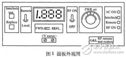
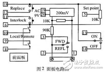
As can be seen from the panel design, the panel function keys include RF power switch key, interlock function (interlock) test button, RF source output power setting knob, RF source forward/reverse power measurement switch, and reset button. There are also displays and indicators on it. Its circuit diagram is shown in Figure 2.
The following briefly describes each function key:
(1) RF power 丌 key: RF ON is the output RF power, OFF is the off RF power.
(2) RF source output power setting knob: set the size of the RF output power.
(3) RF source forward/reverse power measurement switch: measure the magnitude of the forward/reverse power and obtain its reading from the meter.
(4) Reset button: System reset.
Next, in order to realize the analog REMOTE control function, the circuit design is carried out, and the circuit schematic diagram is shown in Fig. 3.
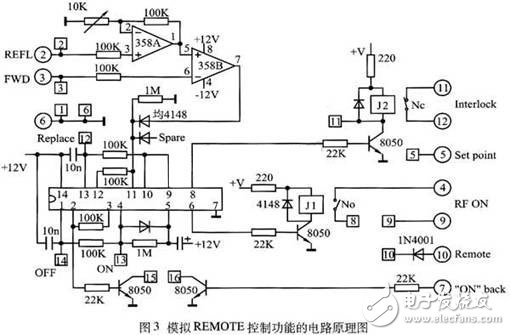
The signal is transmitted through a 15-pin dual-row D-type plug, in which 2 feet receive reverse power, 3 feet receive forward power, 4 feet, 9 feet send RFON signal, 5 feet send SET POINT signal, 6 feet are signal ground, 7 The foot is the ON return signal, and the 11 and 12 feet are the INFERLOCK signal.
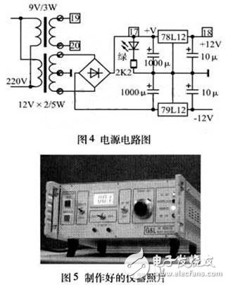
Finally, according to the requirements of the circuit with the corresponding power supply, see Figure 4. Among them, the use of 78L12, 79L12 makes the output voltage more stable. Such a RF source REMOTE control function simulator is designed. Through the circuit welding, assembly, the final production of the entire instrument, as shown in Figure 5.
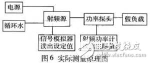
2 practical applicationWhen actually testing the RF source, a set of RF power meter is needed. By comparing the set value with the actual value, it is determined whether the RF source is good or bad. Figure 6 is a schematic diagram of the actual measurement.
Organize your cabling
- Organizes all types of cables
- Ideal for network Patch Panel cabling
- Finger duct design allows easy cable organization
- Cable pass-through holes in the back of the duct
- Only set up 1U rack
- Work with threaded, round and square hole racks
- EIA 19" RACK standard compliable
- Including screws and mounting hardware
Metal Cable Management,1U Metal cable management,stainless steel cable management,metal cable tie mount
NINGBO UONICORE ELECTRONICS CO., LTD , https://www.uniconmelectronics.com
