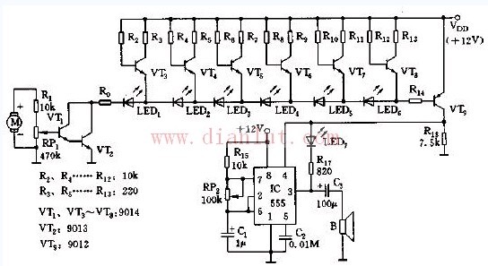
As shown in the figure, the vehicle speed detection signal is taken from the generator of the original speed measurement system, and is added to the strip display diode circuit by Darlington composite amplification. The faster the vehicle speed, the higher the b-pole potential of VT1, the lower the c-pole potential of vt2, the more the LEDs are brighter, and the full-speed, adjust RP1, so that all LED tubes are bright. The strip display formed by the LEDs of the LEDs can replace the original pointer type tachometer. At overspeed, the b-pole potential of VT9 is low, making VT9 saturated and 555 energized. 555 and Rl, RPz, cL, etc. constitute an astable multivibrator. Once it is energized, it oscillates. The vibrating frequency f=1.44/(R15+RP2)C1, the oscillation frequency of the illustrated parameter is about 10Hz~2000Hz. Range, adjust RP2, make the alarm sound volume, LED7 interval flashing.

PoE Switch,PoE Injector, PoE Splitter, PoE Extender, PoE Adapter,PoE Repeater
Chinasky Electronics Co., Ltd. , https://www.chinaskyswitches.com
