Around us, many sensors that capture information are resistive, such as NTC sensors, PTC sensors, LDR sensors, and contact sensors. If the resistance of such sensors is converted to frequency or pulse duration, these parameters can be measured using most microcontrollers (MCUs) without the need for an analog-to-digital converter (ADC).
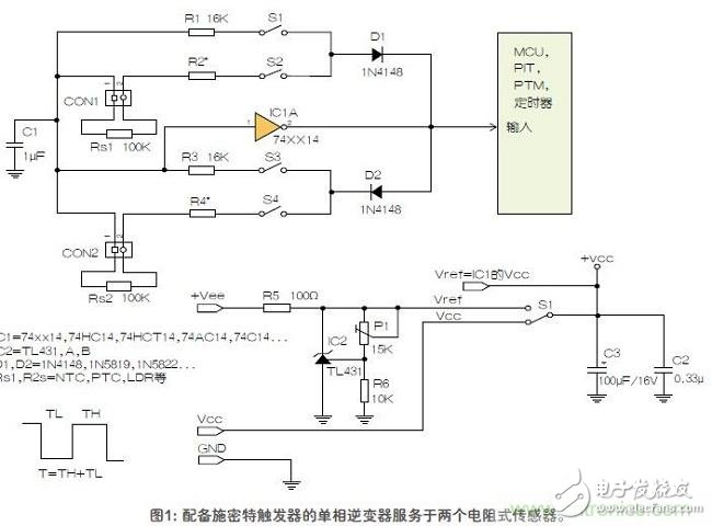
As can be seen from Figure 1, how a single-phase inverter equipped with a Schmitt trigger (xxxx14 or 40106) serves the two resistive sensors Rs1 and Rs2. One of the sensors controls the low time TL of the output pulse, while the other sensor controls the high time TH.

The two diodes D1 and D2 allow the high and low times to be independent of each other. The two resistors R2 and R4 are not necessarily equipped. If necessary, R2 and R4 can be equipped to offset the resistance of the sensor.
To change the sensor response curve or provide a threshold calibration point, use R1 and R3.
The following is an example of a setup circuit, R1 and R3 are used in this example to calibrate the setpoint.
1. If you need to obtain the value of the reference voltage Vref to achieve higher accuracy, set S5 to the top, and set the Vref to the desired value with the trimming potentiometer P1, such as 5.0V, 5.5V, 4.5V, etc. .
2. Switches S1 and S3 are closed and switches S2 and S4 are open. At this point, R1 and R3 determine the high and low time of the output signal.
3. The high level and low level times are measured, and the measurement data is saved to the MCU's memory.
4. Then, switches S2 and S4 are closed, and switches S1 and S3 are open. At this position, sensors Rs1 and Rs2 determine the high and low time of the output signal.
5. The MCU measures the high and low time and compares the measured value with the stored reference data.
The resistance values ​​of the resistors R5, R6, and P1 around the reference source IC2 are determined by a specific implementation, and can be easily calculated according to the formula in the data sheet of the TL431A or equivalent IC.
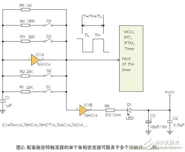
Monitoring multiple contact sensors with a single single-phase inverterA single single-phase inverter can also retrieve information from one or more contact sensors or switches. It can be seen from Figure 2 how a single single-phase Schmitt trigger acquires information for four contact sensors (including S1, S2, S3, and S4). This circuit converts the resistance in the feedback circuit IC1A to a frequency. In this circuit, a diode can also be added as shown in Figure 1 to increase the number of contact sensors.

In this circuit, there are a total of 16 combinations of opening and closing of the switch. Each combination produces a square wave with a predetermined frequency. For calibration, the frequency can be measured and the measurement data will be saved to the memory of the embedded MCU. R5 can be used to maintain oscillation when all switches are turned on. Resistors R1 and R5 can be used with appropriate values. The key point is that each combination of the open and close switches must correspond to a different frequency.
IC1B, R6 and D1 are not necessarily equipped. If desired, IC1B, R6, and D1 allow people to more intuitively identify certain combinations of open and close switches.
The number of Touch sensors is limited only by the resolution and accuracy achieved. The resolution and accuracy achieved depend on the IC, power supply stability, the accuracy of the feedback circuit resistors, and the MCU's ability to measure pulse time and frequency.
For Xiaomi Oca,Redmi Oca Sheet Paper,Screen Oca Glue Paper,Oca Paper Sheet
Dongguan Jili Electronic Technology Co., Ltd. , https://www.ocasheet.com
