This article talks about the Adaptive Cruise Control System (ACC), the first part of which discusses the "ring-sensing system" and the FM continuous-wave (FMCM) radar system, which is the basis of the all-weather ACC system.
This article refers to the address: http://
Ring car sensing system
Almost every minute, people lose their lives in traffic accidents, and the number of injured people is even more countless. In addition, the economic losses caused by traffic accidents have also become astronomical figures. Therefore, automakers and component suppliers have been working to avoid traffic accidents, even if they are not completely preventable, at least to reduce the damage caused by traffic accidents. A large part of the improvement in car safety performance is attributed to the development of automotive electronics.
An analysis of the correlation between vehicle collisions and driver response shows that a large number of traffic accidents can be avoided by the driver detecting the danger in time and making appropriate maneuvers. To meet this requirement, we can provide the driver with an appropriate warning signal or have the vehicle equipped with automatic longitudinal and lateral control functions (driver assistance system). We also need appropriate sensors to detect possible hazards. These sensor networks must cover the entire body and provide the appropriate human-machine interface.
The electronic ring induction system forms the basis of many driver assistance systems that issue warnings or actively intervene. One of the goals of the driver assistance system is to avoid frontal collisions. The hazard warning system and the active brake control system can significantly reduce such accidents. The adaptive cruise control system (ACC) is the first step to achieve this goal.
Most of the existing ACC systems are based on millimeter wave radar, which are mainly divided into pulse system and continuous wave system; and continuous wave system can be divided into frequency modulated continuous wave system (FMCW) and spread spectrum system. The 77 GHz FMCW radar can detect objects within 1-150m and calculate their relative distance and speed from the car. This type of radar can further distinguish the angle between the object and the longitudinal axis of the vehicle by installing an appropriate number of antennas.
Ring car sensing system - adaptive cruise control
The ring-sensing system (see figure below) forms the basis of many driver assistance systems, which are divided into:
Ultrasonic, radar, visual recognition and navigation systems;
Passive and active systems;
Safety system and comfort system;
Driving support, passive safety, collision buffering or vehicle control systems based on their function within the system;
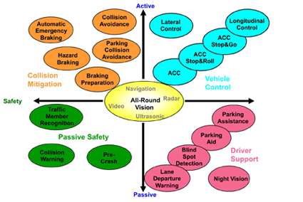
The adaptive cruise control system is part of the vehicle control function that actively intervenes in the longitudinal control of the vehicle. If the distance between the vehicle and the preceding vehicle is less than the preset minimum distance, then they will force the vehicle to slow down; if the distance between the front and rear vehicles is far enough, they will accelerate the vehicle to the set speed. At present, the adaptive cruise control system installed in the vehicle is considered to be comfortable for driving. The maximum degree of intervention for the brakes is only 30% of the braking force, and the final control of the vehicle control is in the hands of the driver. Therefore, the existing adaptive cruise control system is particularly suitable for roads with less traffic density, such as expressways or highways.
Future adaptive cruise control systems will use more sensors, making them suitable for busy urban roads. People can further develop ACC Stop-And-Roll (S&R) and ACC Stop-And-Go (S&G) functions, allowing the vehicle to automatically stop and re-enter between driving, so that the lane will become safer. The traffic flow will be smoother. The ultimate goal of these driver assistance systems is to include 360 ​​degrees around the body and expand the adaptive cruise control system to provide complete longitudinal control.
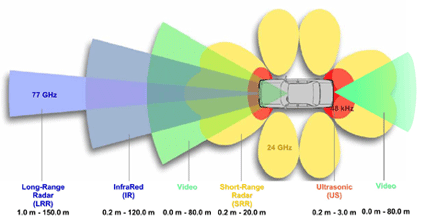
Sensor for the ring sensor system
As shown above, there is a need for a range of different sensors around the body. Both infrared (IR) and long range radar (LRR) sensors are well suited for ACC systems. Infrared sensors can be used in LIDAR (light detection and ranging) systems with detection distances up to 120 meters; 77 GHz long range radar sensors can be extended to 150 meters. Compared with LRR sensors, IR sensors have a price advantage, but they also have the obvious disadvantage that in harsh climates (such as heavy rain, snow, fog or sandstorms), the monitoring distance will be greatly shortened. On the other hand, radar sensors are almost immune to the weather. Another advantage of radar sensors is that they can be concealed to the front of the car. For example, the 77 GHz radar antenna is small and can be mounted almost anywhere on the body. Therefore, most adaptive cruise control systems today use 77 GHz long-range radar.
The main task of the ACC system is to decelerate the vehicle when the distance between the preceding vehicles is too close, and accelerate when the distance is far enough. The control parameters required to complete this task - vehicle speed and reaction time (see the lower control circuit diagram) are set by the driver through the Human Machine Interface (HMI) (see Figure 2 (block diagram) below). The entire control function is provided by the Sensor Control Unit (SCU). The main function of the SCU is to control the sensor and target identification of the ACC system. The control parameter calculation and related system startup are performed by the Electronic Control Unit (EUU) of the ACC system.
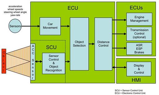
The received signal of the ACC system sensor needs further processing. When the target is identified, the system calculates the distance and relative speed of the potential object based on the information contained in the signal. The distance control needs to accurately lock one of the targets detected by the ACC radar system; the target of the vehicle movement, such as acceleration, wheel speed, steering angle and yaw rate, is used when the target is locked. The ACC system also calculates the minimum required distance based on the speed of the drive itself and the required reaction time.
If the calculated distance is too close at the current speed, the ACC system will send a deceleration command to the appropriate system (such as engine management, brake system) to adjust the distance. If the adjusted distance is sufficient, the speed will be adjusted to the desired speed. To do this, the ACC system must issue an acceleration command to the relevant driver. If the vehicle is unable to maintain the minimum distance, the system will display the set reaction time and warning signal on the display unit. The figure below shows the components of the adaptive system and their relative position on the body.
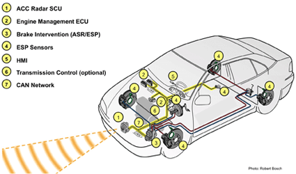
Note: Front-wheel drive car
ASR = accelerated slip control (traction control)
ESP=Electronic Stability System (Electronic Stability Control)
Frequency modulated continuous wave radar system
Most of the existing adaptive cruise control systems use millimeter wave radar systems, among which the frequency modulation continuous wave technology (FMCW) is the most widely used. The FMCW radar system simultaneously detects the distance and speed of the target relative to the vehicle. If an appropriate number of antennas are installed, they can also calculate the angle between the target and the longitudinal axis of the vehicle.
During the modulation period (tm), the transmit frequency of the FM continuous wave radar is continuously changed within the frequency offset range (modulation range, fh) in a linear manner. Figure A below is a transmission signal frequency curve containing three-segment ramps. In a static system where both the transmitter and the target are not moving (see Figure B), the frequency of the received signal lags behind the transmitted signal, and the frequency difference is proportional to the distance between the transmitter and the object. Mixing the transmitted signal with the received signal produces a lower frequency intermediate frequency signal, the maximum of which is called the beat frequency (fb).
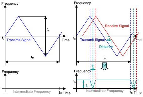
Figure A, Figure B
If the object is moving relative to the transmitter, the frequency of the received signal will change due to the Doppler effect. When the object approaches, the frequency of the received signal increases, and when the object moves away, it decreases. If the distance between the transmitter and the object is ignored, the relative frequency vrel is close to produce the received signal in Figure C below, at which time the intermediate frequency fd remains unchanged. Adding the frequency curves in Figure B and Figure C together to obtain a complete received signal, the intermediate frequency signal contains information such as the distance and relative speed between the transmitter and the target (see Figure D).
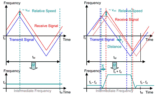
Figure C, Figure D
Figure E and Figure F below are the frequency curves of the transmitter and the object at a relative speed vrel away.
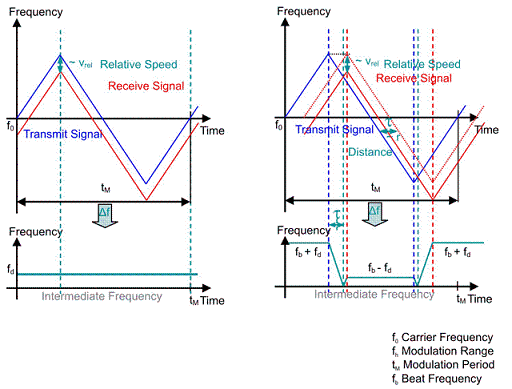
Figure E, Figure F
The intermediate frequency can be expressed as a function of the distance r and the relative velocity vrel by the FM continuous wave radar equation, wherein the addition represents that the transmitter is gradually approaching the target, and the subtraction represents a gradual distance.
When c = speed of light
![]()
The other part of this paper discusses the hardware and software implementation of the ACC system, as well as radar functions and algorithms.
Diesel Generator,Xcmg Diesel Power Set,Trailer Type Generators,Marine Diesel Generator Set
XCMG E-Commerce Inc. , https://www.xcmg-generator.com
