A frequency measurement system with high reliability, high precision, simple use and easy maintenance is proposed and developed, which is used in the field of power electronic measurement. The hardware system uses embedded PC104 computer as the measurement and control platform, and the software system uses LabWindows/CVI as the development platform. The measurement cycle method is adopted, and different reference frequencies are selected according to the frequency. The actual test proves that the design meets the requirements of accuracy and real-time, and the detection efficiency is high, which is convenient for operation and maintenance. The system can also be used in other fields where high precision frequency measurements are required.
1 Introduction
Frequency is a basic physical quantity in a power electronic system, and its measurement problems are very important in engineering applications. The usual measurement scheme is to use a microcontroller or a programmable logic device. However, in some special occasions, the working environment is harsh, requiring high measurement accuracy and high reliability, it is difficult to meet the requirements using conventional solutions, or the cost is too high. In this paper, a frequency measurement system based on PC104 measurement and control computer is proposed. According to the frequency of the frequency to be tested obtained by preliminary test, different reference frequencies are selected, the measurement accuracy reaches 0.2%, and the frequency of simultaneous measurement of multiple signals is realized.
2 overall design
The frequency of the alternating signal refers to the number of times the signal changes periodically in a unit of time, that is, fx = N/t, and the visible measurement fx must use N or t as a reference to measure the other quantity [1]. There are two basic methods for measuring frequency: one is the frequency measurement method, and the standard gate signal t = Tr is given by the measurement circuit to measure the number of times the signal to be tested repeats the change N within a certain time interval Tr, and the signal to be measured is obtained. The frequency is; the other method is the measurement period method, the standard frequency signal fr is provided by the measuring circuit, and the period of the signal to be measured is used as a gate, and the number N of standard signals fr in a measured signal period is measured, and the measured value is obtained. The frequency of the signal is . Both methods have ±1 quantization error of the counter, relative error of the frequency measurement method, and relative error of the measurement period method. The former fx is located in the denominator, and the larger the value is, the smaller the error is. Therefore, the high frequency signal has higher precision, and the latter fx is located in the molecule. The smaller the value is, the smaller the error is, and the measurement precision for the low frequency signal is higher. In this paper, based on the measurement cycle method, the proposed frequency measurement scheme is shown in Figure 1. The PC104 measurement and control computer is used as the hardware platform, and the conditioning module is designed to adjust the signal. It is input to the operating system platform through the PC104 bus, processed by the data processing algorithm, and displayed on the liquid crystal display.
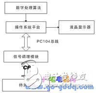
Figure 1 Schematic diagram of the frequency measurement scheme
3 hardware design
In this paper, the PC104 measurement and control computer is used as the hardware platform. The selected functional modules are DMM-32X-AT, OMM-XT and GPIO-MM-XT, which can realize simultaneous measurement of multiple frequency signals. The PC104 is fully compatible with standard desktop PC (PC/AT) architectures and features compact size, small size, low power consumption, wide temperature range (-45°C to 85°C), and high reliability (single module MTBF) 200,000 h), anti-harsh environment, sturdy and durable, etc., thus ensuring the product life cycle [2-3].

Figure 2 Block diagram of the traditional periodic method of frequency measurement
The multi-channel frequency signals to be tested are classified, and the frequency signals having the successive test sequences are shared by a set of detection circuits for conditioning, and the switches between the signals are realized by using the multi-way switches. In the measurement process, the actual input signal has problems such as uncertainty and jitter. In order to improve the measurement accuracy, the signal to be measured is preprocessed, and the high frequency interference and low frequency drift signals are filtered by the filter, followed by linear amplification, and then The zero comparator is shaped into a rectangular wave signal, and finally the PC104 function module card is input through the bistable circuit.
The traditional measurement cycle block diagram is shown in Figure 2. In one cycle of the frequency to be tested, the high-level time counter gate is opened for counting, and the low level is turned off, and the signal period is calculated by measuring the high-level time. However, if there is interference, the count will produce a pulse reading error when the rising and falling edges of the frequency to be tested change slightly. At the same time, for signals with unknown duty cycle, the exact frequency cannot be measured by this principle.
Therefore, in order to reduce the error and measure the signal with unknown duty cycle, the proposed frequency measurement scheme first divides the signal to be tested, so that the frequency measurement time is an integer multiple of the period of the frequency signal to be tested, and the duty ratio Nothing, as shown in Figure 3. In addition, for high frequency and low frequency signals, different frequency division coefficients are used to improve measurement accuracy. A signal of 1 kHz or less is divided by two, and a signal of 1 kHz or more is divided by four.
The hardware circuit schematic is shown in Figure 4.
![]()
Figure 3 is a block diagram of the improved frequency measurement method.
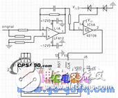
Figure 4 hardware circuit diagram
4 software design
NI LabOS/CVI is selected as the software development environment. It is based on ANSIC and combines tools such as data acquisition, analysis and display to provide an ideal software development environment for automatic detection systems. When there are many signals to be tested, if a single thread is used, it will cause measurement or incentive conflicts, resulting in system crash, and it is difficult to guarantee real-time performance. To avoid this phenomenon, in the frequency measurement program, this article uses the multi-threading technology - thread pool. The thread pool implements multiple tasks to share the CPU in a time-sharing manner, and can complete multiple tasks in parallel in one time period, which is suitable for tasks that need to be executed multiple times or in a loop [4]. At the same time, the software uses the SQLToolkit toolkit to record test data and perform offline data analysis. The software system diagram is shown in Figure 5. In order to measure multiple signals, three functional modules are used for simultaneous measurement.
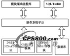
Figure 5 Schematic diagram of the software structure
4.1 DMM-32-XT module frequency measurement
The DMM-32-XT has an onboard frequency of 10 kHz and 10 MHz. Depending on the input frequency, different onboard frequencies are used for measurement. First, the frequency is measured at 10 kHz. The counter is a method of reducing the number of counts, so when a low level is detected, an initial value of 0 is given to the counter 0; when a high level is encountered, the counter automatically starts to count down. Stops until it encounters a low level again. At this time, the value in the counter is latched and read. First read the low low from the counter and then read the high high. The frequency can be found as:
In order to make the measurement error less than 0.5%, fx≤50, if the frequency to be tested is more than 50Hz after frequency division, for higher precision, the on-board frequency of 10MHz will be used for measurement again, the process is the same. The program flow chart is shown in Figure 6.
4.2 OMM-XT module frequency measurement
The OMM-XT module has only one onboard frequency of 4MHz. When the low frequency is measured, with 4MHz as the reference frequency, the counter will overflow. To solve this problem, the counter 1 and the counter 2 are cascaded, and the output of the counter 1 is set as the input of the counter 2. Counter 1 divides the 4 MHz to produce a square wave of 50 kHz, and counter 2 counts this frequency as the reference frequency. When measuring high frequency, only the counter 2 can be used for frequency measurement.
In order to make the measurement error less than 0.5%, fx ≤ 250, in order to retain a certain margin, when fx ≥ 200 is set, the high frequency mode is replaced, that is, only the counter 2 is used for frequency measurement. Similarly, by
When fx ≤ 20 kHz, when the frequency of the signal to be tested is greater than 20 kHz, the accuracy cannot be guaranteed, so the method is only applicable to frequencies below 20 kHz.
4.3 GPIO-MM-XT module frequency measurement
The GPIO-MM-XT function module is an FPGA-based PC104 counter and digital I/O module embedded in two CTS9513 counting logic devices. The onboard frequency is 40MHz, and the software can be configured with 16 frequency division, 256 frequency division, 4096 frequency division and 65536 frequency division to obtain reference frequencies of different sizes. The frequency measurement principle is similar to the above module. The program flow chart is shown in Figure 7.
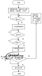
Figure 6 DMM-32X-AT module frequency measurement flow chart
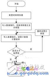
Figure 7 GPIO module frequency measurement flow chart
5 Experimental results
Using the frequency signal generated by the EE1411 type synthesis function signal generator as an input, 10 measurements were made for each signal. The experimental data obtained are shown in Table 1. It can be seen that the measurement error is below 0.2%.
6 Conclusion
In this paper, a high-precision frequency measurement system is discussed in detail. The system fully considers the characteristics of the field use environment and user requirements, and provides convenience for offline data analysis and processing. The PC104 bus module is used on the hardware to ensure high reliability of the system. The software platform adopts NI LabWindows/CVI, and the software design is oriented to the testing process, and the interface is friendly, which provides a good foundation for function expansion. The actual test shows that the system is used in power electronic measurement, meets the corresponding test requirements and test indicators, and has simple operation, good reliability, high detection efficiency, and is easy to carry and maintain.
ZGAR Vape Pods 1.0
ZGAR electronic cigarette uses high-tech R&D, food grade disposable pods and high-quality raw material. A new design of gradient our disposable vape is impressive.We equip with breathing lights in the vape pen and pods.
Our team has very high requirements for product quality, taste allocation and packaging design. Designers only use Hong Kong designers, e-cigarette liquid only imports from the United States, materials are food grade, and assembly factory wants medical grade without ground workshop.
We offer best price, high quality Pod System Vape,Pods Systems Touch Screen,Empty Pod System, Pod Vape System,Disposable Pod device,Vape Pods to all over the world.


ZGAR Vape 1.0 Pods,ZGAR Vape Pods 1.0 ,Pod Systems,Atomizer, E-cigarette, Empty Pod Vape Manufacturer and Supplier in China
ZGAR INTERNATIONAL(HK)CO., LIMITED , https://www.zgarvapor.com
