Construction of DD visual wave amplifier using negative pressure charge pump and analog switch
The MAX9503 / MAX9505 DirectDrive video filter amplifier integrates an analog switch (MAX9505) and a negative pressure charge pump. These devices use a single 2.7V to 3.6V power supply and can be directly connected to the output of the video DAC, placing the black level of the video signal at ground potential at the output. These devices eliminate the need for additional negative power supplies and large output DC blocking capacitors, thereby reducing system cost and saving board area. As can be seen from the discussion below, negative pressure charge pumps and analog switches can improve audio / video system performance.
Using negative pressure charge pump to adjust the level of sync head
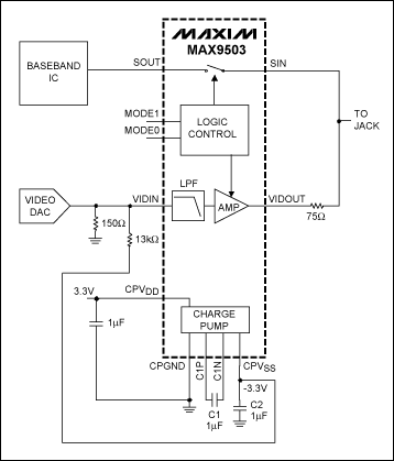
When the MAX9503 / MAX9505 input sync tip voltage range is 0 to 50mV, the output black level is between -0.1V and 0.1V. In some applications, the sync tip voltage output by the DAC can exceed 50mV. In this case, the black level voltage output by the MAX9503 / 5 may exceed 100mV. If the output black level voltage is equal to the ground potential, the input voltage can be adjusted using the circuit shown in Figure 1 to adjust the output black level. Assuming a DAC load of 150Ω, connect a 13kΩ resistor between the input and CPVSS (-3.3V) of the negative pressure charge pump. The resistor divider network shifts the input voltage of the filter amplifier down by about 40mVP-P. Using this resistor divider network, the noise ripple at the input of the filter amplifier is less than 0.5mV and can be ignored.

Figure 1: The output black level is changed by adjusting the input voltage of the MAX9503 / MAX9505.
Use of analog switches for audio / video applications
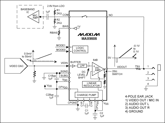
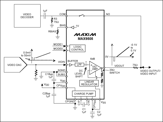
As shown in Figure 2, the MAX9505 integrates an analog switch connected to an external four-hole multimedia socket, and the video output and microphone input share a pin. The switching action is controlled by the logic level of the MODE0 and MODE1 pins. When using the microphone input, the analog switch is closed; the audio signal enters the baseband chip through the switch; the video filter amplifier is disabled, and the output is high impedance. R1 and R2 set the bias voltage of the audio signal to 1.4V. The bandwidth of the analog switch is 200MHz, which is used for video signal switching. Figure 3 shows the application of the MAX9505 in bidirectional video input / output switching. R3 is the 75Ω termination resistor of the external input video signal.

Figure 2: The MAX9505's analog switch is connected to a four-hole multimedia socket.

Figure 3: The MAX9505 is used for bidirectional video signal input / output.
SHAOXING COLORBEE PLASTIC CO.,LTD , https://www.fantaicolorbee.com
