A USB bus interface circuit for embedded system is described in detail. The circuit is implemented based on the USB dedicated chip CH375, and the system hardware implementation and application program are given. The experimental results show that the circuit has the characteristics of low cost and high reliability, and can be easily integrated into various embedded systems.
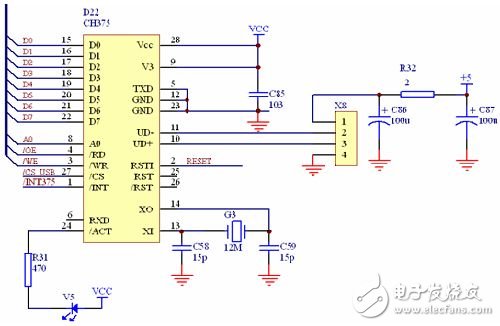
Interface circuit design : The connection mode between single chip microcomputer and CH375 chip is serial interface and parallel interface. Although the serial interface connection mode is simple, the external address space is not extended, but it must follow a certain communication protocol, and the software design is relatively Complex, and the transmission speed is slower than that of the parallel interface. For most embedded system applications, because the serial port resources are few, and the extension of the external address space technology is very mature, the interface circuit adopts the parallel port connection mode. Its circuit schematic is shown in Figure 2.

Figure 2 interface circuit diagram
The X8 in Figure 2 is a USB interface socket. In order to avoid the USB device from accessing the embedded system, the operating current suddenly increases, which interferes with the normal operation of the embedded system. When designing the circuit, a 2 ohm current limiting resistor is added near the USB interface socket to prevent current overload when the USB device is connected. At the same time, a 100μF electrolytic capacitor is added to the USB interface socket power supply. For energy storage and filtering, improve the load and anti-interference ability of the USB port.
In Figure 2, the reset terminal (RSTI) of CH375 is connected to the embedded system reset signal (RESET) to ensure that the CH375 can be reset synchronously when the embedded system is reset. The transmitting end (TXD) determines the working mode of the chip. Pull-up resistor, input low level during reset to enable parallel port, floating or input high level to enable serial port, this interface circuit works in parallel port mode, the transmitting end (TXD) is directly grounded; the crystal oscillation input terminal ( XI) and inverting output (XO), external 12MHz crystal and two 15pF oscillating capacitors provide working clock for the chip; 8-bit bidirectional data bus (D0-D7) directly with the lower 8-bit data bus of the embedded system Connection for data exchange between the two. Read strobe input (/RD), write strobe input (/WR), interrupt request output (/INT) with embedded system read signal (/OE), write signal (/WE) and external interrupt The input terminal (/INT375) is connected; the chip select control input (/CS) is connected to the decoder output (/CS_USB) in the embedded system; the address line input (A0) is used to distinguish between the command port and the data port, and The system address line A0 is connected, and the above control signals are used to control the chip to work according to the correct timing. Some other capacitors of the circuit are mainly used for power supply decoupling and filtering, and will not be described in detail.
Speaker Connectors,Pro Audio Speaker,Audio Speaker Audio System,Tweeter Speaker 20W
NINGBO BOILINGSOUND ELECTRONICS CO.,LTD , https://www.tweeterspeaker.com
