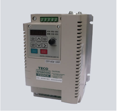
Parameter setting of the inverter
The parameter setting of the inverter is very important during the commissioning process. Due to improper parameter setting, it can not meet the needs of production, resulting in failure of starting and braking, or frequent tripping during operation. In severe cases, the power module IGBT or rectifier bridge will be burnt. The types of inverters are different and the amount of parameters is different.
Generally, the inverter with single function control has about 50 to 60 parameter values, and the inverter with multi-function control has more than 200 parameters. But whether or not the parameters are more or less, do you want to re-adjust all the parameters in debugging? No, most of them can be changed, as long as they are according to the factory value, as long as the original factory value is not suitable for resetting, such as external terminal operation, analog operation, base frequency, maximum frequency, upper limit frequency, The lower limit frequency, start-up time, braking time (and mode), thermal electronic protection, overcurrent protection, carrier frequency, stall protection and overvoltage protection must be corrected. When the operation is not suitable, adjust other parameters.
Several common problems in on-site debugging
The starting time setting principle should be short and not suitable. The specific values ​​are as follows.
The overcurrent setting value OC is too small, and can be increased to a maximum of 150%. The empirical value is 1.5~2s/kW, and the small power is larger; if it is greater than 30kW, it is >2s/kW. Press the start button *RUN and the motor is blocked. Indicates that the load torque is too large and the starting torque is too small (try to increase). At this time, press STOP to stop immediately, otherwise the motor will burn out.
Since the motor does not turn in the locked state, the anti-heating E=0, at this time, the AC impedance value Z=0, only the DC resistance is very small, then, the current is very dangerous, it is necessary to trip the OC action. The braking time setting principle is that the length should not be short, and the overvoltage trip OE is easy to occur.
It is advisable to freely brake the water pump fan, and it is easy to produce a serious "water hammer" effect by implementing fast and strong braking. The starting frequency setting is beneficial to the acceleration start, especially when it is light load. The starting frequency of the heavy load is large, which causes the starting current to increase. It is easier to skip the current OC in the low frequency range. The general starting frequency is suitable from 0. The starting torque setting is beneficial to the acceleration start, especially when it is light load. The starting torque value of the heavy load is large, causing the starting current to increase. It is easier to skip the current OC in the low frequency range. The general starting torque starts from 0. Suitable.
The base frequency setting base frequency standard is 380V at 50 Hz, that is, V/F = 380/50 = 7.6. However, due to heavy load (such as extruder, washing machine, dryer, mixer, mixer, dewatering machine, etc.), it is often impossible to start, and adjusting other parameters often does not help, then adjusting the substrate frequency is an effective method. The 50Hz set value is lowered, and can be reduced to 30Hz or below. At this time, V/F>7.6, that is, the output voltage is increased at the same frequency, especially at a low frequency band (ie, torque âˆU2). Therefore, the heavy load can be started normally. Overvoltage during braking The overvoltage during braking is caused by the short braking time and the braking resistor value being too small. By increasing the resistance time, the resistance value can be avoided.

Choice of braking method
(1) Energy consumption braking. With general braking, the energy is dissipated in the resistance and is lost in the form of heat. At lower frequencies, the braking torque is too small to cause creep.
(2) DC braking. Applicable for precise parking or parking, no creeping, can be used in combination with energy braking, generally with DC braking at ≤20Hz, and with energy consumption at >20Hz.
(3) Feedback brake. Applicable ≥100kW, speed ratio D≥10, alternating high and low speed or alternating positive and negative, the cycle time is also short. In this case, feedback braking is applied, and the feedback power can reach 20% of the motor power. More specific details analysis and parameter selection. No-load (or light-load) jump OC is reasonable when no-load (or light load), the current is not large, should not jump OC, but this phenomenon has actually occurred, the reason is often the compensation voltage is too high, starting torque If it is too large, the excitation saturation will be severe, causing the excitation current to be severely distorted, causing the spike current to be too large and tripping OC, and appropriately reducing or restoring the factory value or placing it at the 0 position.
The reason for jumping OC at low frequency ≤20Hz at start-up is due to over-compensation, large starting torque, short starting time, too small protection value (including over-current value and stall over-current value), and the base frequency can be reduced. Difficult to start, can not start the general equipment, the moment of inertia GD2 is too large, the resistance torque is too large, and heavy load start, large fans, pumps and other similar situations often occur, the solution:
1 reduce the substrate frequency;
2 appropriately increase the starting frequency;
3 Appropriately increase the starting torque;
4 reduce the carrier frequency value of 2.5 ~ 4kHz, increase the effective torque value;
5 reduce the starting time;
6 increase the protection value;
7 The load is converted from no-load start to no-load or light load, that is, the small inlet valve can be closed to the fan. After using the inverter, the temperature rise of the motor is increased, the vibration is increased, and the noise is increased. Our carrier frequency setting value is 2.5 kHz, which is lower than the usual one. The purpose is to use safety from the perspective, but it is more common to reflect the above three problems. After increasing the carrier frequency value, the problem is solved.
After power transmission, press the start button RUN and no response
(1) The panel frequency is not set;
(2) The motor does not move. In this case, immediately press “STOP STOP†and check the following items:
1 Confirm the correctness of the line again;
2 reconfirm the determined code (especially for the part related to the start);
3 Run mode setting is correct;
4 measuring input voltage, R, S, T three-phase voltage;
5 measuring the DC PN voltage value;
6 measuring the voltage value of each group of switching power supplies;
7 check the contact of the driver circuit plug-in;
8 Check the contact status of the panel circuit plug-in;
9 After a full inspection, the power can be turned on again.

The 45W MagSafe Power Adapter has a magnetic DC connector, so if someone trips on it, the power cord disconnects harmlessly, keeping your MacBook Air safe. It also helps prevent the cable from fraying or weakening over time. Additionally, the magnetic DC helps guide the plug into the system for a quick and safe connection.
45W Macbook charger air,macbook 45watt charger,45W Macbook pro charger
Shenzhen Waweis Technology Co., Ltd. , https://www.laptopsasdapter.com
