Button and interrupt section
Take the button to trigger interrupt as an example, talk about the interrupt system of S5PV210
To use interrupts, we must first do two parts of work: CPU interrupt initialization and the corresponding device interrupt initialization. CPU interrupt initialization: it is necessary to set up the CPU interrupt related things. Interrupt initialization of related devices: For example, our button, we must set up the button, so that as soon as the button is pressed, it will trigger an interrupt.
(1) Let's talk about the related interrupt settings of the button first

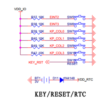
First look at the hardware connection of the buttons: we can see that the buttons are connected at EINT2 and EINT3, and there are KP_COL0-3, a total of 6 buttons, and then we look at the interface of the SOC, you can see that EINT2 and EINT3 are connected At GPH0_2, 3, KP_COL0-3 was connected to GPH2_0-3

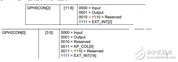
Then, we look up the datasheets of GPH0 and GPH2, and set them all to the external interrupt mode (EXT_INT) mode, which is 1111. KP_COL mode is used for matrix keyboard.

After setting the registers GPH0 and GPH2, we set the following registers related to external interrupts: EXT_INT_0_CON, EXT_INT_2_CON, EXT_INT_0_MASK, EXT_INT_2_MASK, EXT_INT_0_PEND, EXT_INT_2_PEND.
Summary: That is to say, on the button side, if you press a button, you only need to set four registers to work.
GPH0CON selects external interrupt mode,
EXT_INT_0_CON selects how to trigger the interrupt (high level triggers the interrupt, or low level, rising edge, falling edge, rising/falling edge trigger interrupt),
EXT_INT_0_MASK: Write 0 to this register to enable interrupts;
EXT_INT_O_PEND: When we initialize, we can write 1 to clear the interrupt. After the interrupt is processed, we also need to write 1 to this register to clear the interrupt. After setting the above registers, the interrupt initialization of our button part is set. 
1 // Handle the initialization of keys by interrupt
2 void key_init_interrupt (void)
3 {
4 // 1. GPIO mode setting corresponding to external interrupt
5 rGPH0CON |= 0xFF "《8; // GPH0_2 GPH0_3 is set to external interrupt mode
6
7 // 2. Interrupt trigger mode setting
8 rEXT_INT_0_CON &= ~(0xFF《《8); // bit8~bit15 are all cleared
9 rEXT_INT_0_CON |= ((2《《8)|(2》《12)); // EXT_INT2 and EXT_INT3 are set to trigger on the falling edge
10
11 // 3. Interrupt enable
12 rEXT_INT_0_MASK &= ~(3《《2); // External interrupt enable
13
14 // 4. Clear to suspend, clear is to write 1, not to write 0
15 rEXT_INT_0_PEND |= (3《《2);
16}
(2) Set the interrupt mode of the CPU
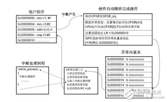
1. When the interrupt is generated, the general process of the work done by the CPU

Image source: http://blog.csdn.net/mr_raptor/arTIcle/details/6556195
It should be noted that: 1. When an external interrupt occurs, the EXT_INT_O_PEND register (the register on the side of the button) is set to 1, and the interrupt is suspended. This is equivalent to telling the CPU that an interrupt has occurred, and then the CPU has occurred. response
2. After the interrupt occurs, the IRQ interrupt bit in the cpsr register is set to 1, so after the CPU comes in to handle the interrupt, if other hardware has an interrupt during this time, the CPU will ignore it.
According to the above picture: what we want to accomplish is:
1. Put our exception handling entry address into the memory corresponding to our exception vector table: 0x00000018
2. The process corresponding to the picture of the exception handling entry above, the specific implementation code is as follows.
1 IRQ_handle:
2 // Set the stack in IRQ mode
3 ldr sp, =IRQ_STACK
4 // Save LR
5 // Because ARM has a pipeline, the value of PC will be +8 higher than the code actually executed,
6 sub lr, lr, #4
7 // Save r0-r12 and lr to the stack in irq mode
8 stmfd sp! , {R0-r12, lr}
9 // Call real isr here to handle interrupt
10 bl irq_handler
11 // The processing is completed and the restoration of the scene is started. In fact, the interrupt is returned. The key is to reply r0-r12, pc, cpsr together
12 ldmfd sp! , {R0-r12, pc}^
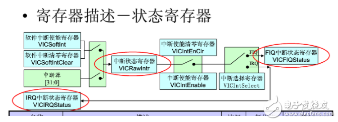
2. Set the interrupt related registers, let the CPU find the corresponding execution program, and then execute it (this is the purpose of the interrupt: execute the interrupt handler)

Image source: http://
Related registers are: VICnADDR VICnINTENCLEAR VICnINTSELECT VICnIRQSTATUS VIC0VECTADDRn VICnINTENABLE
1.VICnADDR: There are four registers, one for each VIC (0-3), used to store the address of the interrupt handler (isr) that we want to execute. The address in it is from the register VIC0VECTADDRn, When the interrupt occurs, the address in VIC0VECTADDRn will be automatically flushed to this register by hardware. (After interrupt processing is completed, we have to clear this register)
1 // Clear the address of the interrupt processing function of the interrupt that needs to be processed
2 void intc_clearvectaddr (void)
3 {
4 // VICxADDR: the address of the interrupt processing function of the interrupt currently being processed
5 VIC0ADDR = 0;
6 VIC1ADDR = 0;
7 VIC2ADDR = 0;
8 VIC3ADDR = 0;
9 }
2.VICnINTENCLEAR: Clear the interrupt register, that is, after the interrupt processing is completed, we have to write 1 to this register to clear the interrupt. We can also disable that interrupt by the corresponding interrupt number.
1 // Disable interrupt
2 //A specific interrupt source is prohibited by passing intnum. The interrupt number is defined in int.h, which is the physical interrupt number
3 void intc_disable (unsigned long intnum)
4 {
5 unsigned long temp;
6
7 if (intnum "32"
8 {
9 temp = VIC0INTENCLEAR;
10 temp |= (1 "intnum";
11 VIC0INTENCLEAR = temp;
12}
13 else if (intnum "64"
14 {
15 temp = VIC1INTENCLEAR;
16 temp |= (1 "" (intnum-32));
17 VIC1INTENCLEAR = temp;
18}
19 else if (intnum "96"
20 {
21 temp = VIC2INTENCLEAR;
22 temp |= (1 "" (intnum-64));
23 VIC2INTENCLEAR = temp;
twenty four }
25 else if (intnum "NUM_ALL"
26 {
27 temp = VIC3INTENCLEAR;
28 temp |= (1 "" (intnum-96));
29 VIC3INTENCLEAR = temp;
30}
31 // NUM_ALL: disable all interrupt
32 else
33 {
34 VIC0INTENCLEAR = 0xFFFFFFFF;
35 VIC1INTENCLEAR = 0xFFFFFFFF;
36 VIC2INTENCLEAR = 0xFFFFFFFF;
37 VIC3INTENCLEAR = 0xFFFFFFFF;
38}
39
40 return;
41}
3.VICnINTSELECT: Interrupt selection register, we choose FIQ mode or IRQ mode here
1 // Initialize the interrupt controller
2 void intc_init (void)
3 {
4 // Disable all interrupts
5 // Why should all interrupts be disabled at the beginning of interrupt initialization?
6 // Because the interrupt is turned on, it will always look for isr after the interrupt is generated due to external or hardware reasons.
7 // And we may think that if we don’t use this interrupt, we don’t provide the isr.
8 // The program is likely to run away, so unused interrupts must be turned off.
9 // The general approach is to turn off all of them first, and then turn on the interrupts you are interested in one by one. Once opened
10 // Provide the corresponding isr for this interrupt and bind it.
11 VIC0INTENCLEAR = 0xffffffff;
12 VIC1INTENCLEAR = 0xffffffff;
13 VIC2INTENCLEAR = 0xffffffff;
14 VIC3INTENCLEAR = 0xffffffff;
15
16 // Select interrupt type as IRQ
17 VIC0INTSELECT = 0x0;
18 VIC1INTSELECT = 0x0;
19 VIC2INTSELECT = 0x0;
20 VIC3INTSELECT = 0x0;
twenty one
22 // Clear VICxADDR
23 intc_clearvectaddr();
twenty four }
4.VIC0VECTADDRn: There are 128 such registers, one interrupt number corresponds to one such register, we can calculate the address of the VIC0VECTADDRn register by the interrupt number and the base address of VICnADDR, and then put our execution program in this register , So that we don't need to define too many macros.
1 // Bind the isr we wrote to the VICnVECTADDR register
2 // After binding, we will hand over the isr address to the hardware, we don’t need to control the rest, the hardware will handle it by ourselves
3 //When the corresponding interrupt occurs, we can go directly to the corresponding VICnADDR to get the isr address.
4 //Parameter: intnum is the physical interrupt number defined by int.h, handler is the function pointer, which is the isr we wrote
5
6 // VIC0VECTADDR is defined as the address of the VIC0VECTADDR0 register, which is equivalent to VIC0VECTADDR0~31
7 // The first address of the array (this array is an array of function pointers), and then calculate each interrupt specifically
8 // Only the first address + offset is required.
9 void intc_setvectaddr (unsigned long intnum, void (*handler) (void))
10 {
11 //VIC0
12 if (intnum "32"
13 {
14 * ((volaTIle unsigned long *) (VIC0VECTADDR + 4* (intnum-0))) = (unsigned) handler;
15}
16 //VIC1
17 else if (intnum "64"
18 {
19 * ((volaTIle unsigned long *) (VIC1VECTADDR + 4* (intnum-32))) = (unsigned) handler;
20}
21 //VIC2
22 else if (intnum "96"
twenty three {
24 * ((volaTIle unsigned long *) (VIC2VECTADDR + 4* (intnum-64))) = (unsigned) handler;
25}
26 //VIC3
27 else
28 {
29 *( (volatile unsigned long *) (VIC3VECTADDR + 4*(intnum-96))) = (unsigned) handler;
30}
31 return;
32}
5. VICnIRQSTATUS: Interrupt status register in IRQ mode (a total of 4), this register will be automatically set to 1 after an interrupt occurs, and then we determine which of these 4 registers has written 1, and then we know The address of our interrupt execution program is placed in which VICnADDR register, and finally find the address of the interrupt execution program in the corresponding VICADDR register. (I added myself: After reasoning and analysis, I feel that this bit is automatically cleared by hardware after the interrupt is responded to, because we did not clear this bit during the processing of the interrupt, but it was only used during the query, and the software was not cleared. Zeroing this bit does not affect the operation of the program, but you must clear the PEND corresponding to the four VICnADDR registers. As for why you need to clear the VICnADDR registers, it is not clear. If you do not clear these registers, the interrupt will respond once, and then Will no longer respond)
1 unsigned long vicaddr[4] = {VIC0ADDR, VIC1ADDR, VIC2ADDR, VIC3ADDR};
2 int i=0;
3 void (*isr) (void) = NULL;
4
5 for (i=0; i《4; i++)
6 {
7 // When an interrupt occurs, 3 of the 4 VICs are all 0s and one of the 1 is not 0
8 if (intc_getvicirqstatus (i)! = 0)
9 {
10 isr = (void (*) (void)) vicaddr [i];
11 break;
12}
13}
14 (*isr)(); // Call function by function pointer
6. VICnINTENABLE: Interrupt enable register, by interrupt number, to write 1 to the corresponding bit of the interrupt enable register, you can enable the corresponding interrupt
1 // Enable interrupt
2 // Enable a specific interrupt source by passing intnum, the interrupt number is defined in int.h, is the physical interrupt number
3 void intc_enable (unsigned long intnum)
4 {
5 unsigned long temp;
6 // Determine which bit of which register intnum is in
7 // "32 is 0 to 31, which must be in VIC0
8 if (intnum "32"
9 {
10 temp = VIC0INTENABLE;
11 temp |= (1 ""intnum); // If it is the first design, it must be bit operation, the second design can
12 // Write directly.
13 VIC0INTENABLE = temp;
14}
15 else if (intnum "64"
16 {
17 temp = VIC1INTENABLE;
18 temp |= (1 "" (intnum-32));
19 VIC1INTENABLE = temp;
20}
21 else if (intnum "96"
twenty two {
23 temp = VIC2INTENABLE;
24 temp |= (1 "" (intnum-64));
25 VIC2INTENABLE = temp;
26}
27 else if (intnum "NUM_ALL"
28 {
29 temp = VIC3INTENABLE;
30 temp |= (1 "" (intnum-96));
31 VIC3INTENABLE = temp;
32}
33 // NUM_ALL: enable all interrupt
34 else
35 {
36 VIC0INTENABLE = 0xFFFFFFFF;
37 VIC1INTENABLE = 0xFFFFFFFF;
38 VIC2INTENABLE = 0xFFFFFFFF;
39 VIC3INTENABLE = 0xFFFFFFFF;
40}
41
42}
At this point, all the preparation work is completed, just call the corresponding function in the main function.
1 int main (void)
2 {//Serial port initialization uart_init();
3 //Key interrupt initialization
4 key_init_interrupt();
5
6 // If an interrupt is to be used in the program, it is necessary to call interrupt initialization to initially initialize the interrupt controller
7 system_init_exception();
8
9 // Bind the isr to the interrupt controller hardware
10 intc_setvectaddr (KEY_EINT2, isr_eint2);
11
12 // enable interrupt
13 intc_enable (KEY_EINT2);
14
15 return 0;
16}
The ultimate goal: to execute the interrupt handler, as long as we press the button, it will print "isr_eint2_LEFT" on the serial port
1 // The key corresponding to the EINT2 channel is the key corresponding to the GPH0_2 pin, which is the key labeled LEFT on the development board
2 void isr_eint2 (void)
3 {
4 // The real isr should do 2 things.
5 // First, the interrupt processing code is the code that really works
6 printf("isr_eint2_LEFT.");
7 // Second, clear interrupt pending
8 rEXT_INT_0_PEND |= (1《《2);
9 intc_clearvectaddr();
10}
The present invention provides a method for controlling the temperature of a flue-cured electronic cigarette and a flue-cured electronic cigarette. The flue-cured electronic cigarette includes an N-section heating body, where N is an integer greater than 1, and the heating body is used for heating tobacco. The method for controlling the temperature of the flue-cured electronic cigarette includes: the flue-cured electronic cigarette heats the i-th heating body, and i is an integer greater than 0 and less than N; after the first preset time, the flue-cured electronic cigarette pairs the i+ The first stage heating body is heated; after the second preset time, the flue-cured electronic cigarette stops heating the i-th stage heating body, and continues to heat the i+1th stage heating body. The technical solution solves the problem of unbalanced smoke output of flue-cured electronic cigarettes during multi-stage heating.The present invention provides a method for controlling the temperature of a flue-cured electronic cigarette and a flue-cured electronic cigarette. The flue-cured electronic cigarette includes an N-section heating body, where N is an integer greater than 1, and the heating body is used for heating tobacco. The method for controlling the temperature of the flue-cured electronic cigarette includes: the flue-cured electronic cigarette heats the i-th heating body, and i is an integer greater than 0 and less than N; after the first preset time, the flue-cured electronic cigarette pairs the i+ The first stage heating body is heated; after the second preset time, the flue-cured electronic cigarette stops heating the i-th stage heating body, and continues to heat the i+1th stage heating body. The technical solution solves the problem of unbalanced smoke output of flue-cured electronic cigarettes during multi-stage heating.
E-Cigarette Starter Kits,small e cigarette starter kit,mini e cigarette starter kit,e cig starter kit near me,cheapest e cigarette starter kit, e cigarette starter kits,electronic cigarette starter kits
Suizhou simi intelligent technology development co., LTD , https://www.msmvape.com
