This paper presents a design scheme of embedded CNC system based on ARM and FPGA. The hardware and software design of the ARM system, the hardware-based fine interpolation implementation method based on FPGA and the acceleration and deceleration control strategy of the numerical control system are introduced in detail. The system combines the advantages of fast ARM operation and high computational accuracy with the online reconfigurability of FPGA internal logic, which improves resource utilization and real-time performance and enhances the flexibility of the CNC system. The simulation and practice results show that the whole control system has the advantages of good real-time performance, low cost and high performance.
In the existing numerical control system, the computer numerical control system scheme of the industrial computer plus the motion control card is adopted to design the motion controller. With the increasing complexity of the overall function of the industrial computer, the requirements for the size, cost and power consumption of the motion control system are becoming more and more demanding. The existing computer numerical control system gradually presents a disadvantage of serious waste of resources and poor real-time performance in motion control. In addition, the openness, modularization and reconfigurable design of the CNC system is a hot topic in the field of numerical control technology. The purpose is to adapt to the development of technology and to facilitate users to develop their own functions. Based on the hardware platform of ARM and FPGA, this paper designs an embedded CNC system with high openness characteristics by adopting the separation of strategy and mechanism. The numerical control system not only has the main functions of the large-scale numerical control system in the past, but also has better operability and cutting performance, and has more outstanding advantages in terms of openness, making the numerical control system application software portable and interchangeable.
1 Based on ARM and FPGA, the overall scheme of embedded CNC systemThe structure of the embedded CNC system based on ARM and FPGA is shown in Figure 1. According to the idea of ​​module division, this paper divides the controller into three parts: human-computer interaction, interpolation algorithm and communication. ARM in the system uses Samsung's 16/32-bit RISC microprocessor S3C2440A, which uses the ARM920T core with a core frequency of up to 400MHz. The FPGA uses the XC3S250E from Xilinx's Spartan 3E series.
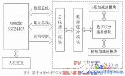
As the control core of the numerical control system, ARM is mainly responsible for decoding, calculating and logic processing the part processing code and control information obtained from the data memory or directly obtained from the upper PC or network, completing the coarse interpolation of the processing data and the man-machine. Interface and data communication. ARM system is the control core of the whole CNC system. Under the management of embedded operating system, the information processing and coarse interpolation operation of the whole system are realized by means of time-sharing processing, and various control commands are input through input devices such as keyboard and touch screen. The real-time running status of the numerical control system is displayed through LCD, indicator light, etc., to achieve human-machine friendly interaction. Based on S3C2440A controller, there are various communication interfaces, including RS232, RS485, Ethernet port, USB and other interface modules. File transfer and network control are implemented through these interfaces.
The overall structure of the embedded CNC software system is shown in Figure 2. The software structure of the system is mainly divided into two parts: operating system software and numerical control application software. Since the numerical control system is a real-time multi-tasking system, the real-time requirements are very high. To ensure the coordinated execution of each task, the system uses the μC/OS-II real-time operating system as a software platform.
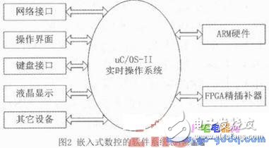
In order to realize the normal operation of the operating system on the S3C2440A microprocessor platform, it is necessary to modify the code related to the processor type. The work required for the operating system migration is to rewrite three files, that is, rewrite the file 0S_CPU. H, 0S_CPU_A. ASM and OS_CPU_C. C. Where 0S_CPU. H includes the processor-related variables, macros, and types defined with the #define statement. 0S_CPU_A. Several assembly language functions are defined in ASM, including the interrupt vector address of the interrupt service routine. If some C compilers allow assembly language statements to be inserted directly into C, they are not necessarily required, and the user can put the required assembly language code directly into OS_CPU_C. In the C file.
3 ARM and FPGA interface designIn order for the system to work as expected, first of all, reliable communication between ARM and FPGA should be implemented from the hardware. The solution adopted in this paper is to implement SRAM timing on the FPGA, and connect the FPGA as a special memory device to the ARM memory address space. In this way, only the driver of the SRAM needs to be written on the ARM side to realize data writing and reading to the FPGA side.
3.1 SRAM Timing
SRAM timing is divided into read timing and write timing. When the CPU reads the SRAM, it first writes the correct address signal on the address line, followed by the chip select signal to the SRAM chip, then the read signal to the chip, and then the CPU is in the data after a certain period of oscillation. Read stable and valid data online.
When the CPU writes to the SRAM, it first writes the correct address line number on the address line, followed by the chip select signal to the SRAM chip, and then the write signal to the chip. The CPU will be at the rising edge of the write signal. The data line is ready for valid data for the SRAM chip to write data to the corresponding address location on the rising edge of the write signal.
3.2 FPGA-side SRAM The interface signals required for ARM and FPGA communication are address line A0-A15, data line D0-D15, chip select signal nCS, read signal nRD and write signal new, each time 16-bit data needs to be realized. Read and write. The SRAM timing is described in the Verilog hardware language as follows:
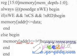
It can be seen that only when the chip select signal and the read signal are both pulled low and the write signal is still high, the value of the corresponding unit on the address line is output on the data line. In other cases, the FPGA sets the data line to a high impedance state. Give up control of the data line.
4 FPGA-based DDA fine interpolator designWith the maturity of FPGA devices and their development technologies, the implementation of motion control using FPGAs shows great potential. Because FPGA design is parallel, multi-threaded, and has online programmability, it combines the advantages of high speed and low cost, while overcoming the lack of flexibility of dedicated processors. FPGA-based DDA fine interpolators have strong advantages over traditional software interpolation.
4.1 Digital Integral Interpolation Algorithm
At present, the more mature numerical control interpolation algorithms include point-by-point comparison method, minimum deviation method and digital integration method. The digital integration method is also called Digital Differen TIal Analyzer (DDA). The method is used for interpolation, which has the characteristics of fast calculation speed, strong logic function and uniform pulse distribution, and can realize one-time, two-time or even high-order curve interpolation, and is easy to realize multi-axis linkage.
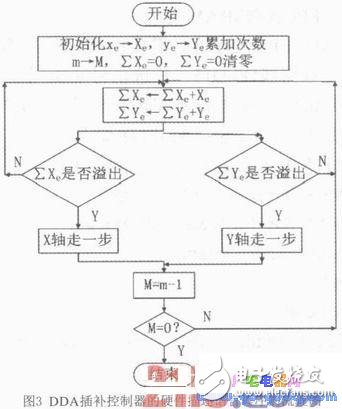
The digital integral interpolation algorithm is a summation operation that converts the integral operation of a function into a variable. If the selected pulse equivalent is small enough, the error caused by the summation operation instead of the integral may not exceed the allowable value. Two registers (function register and accumulating register) and a full adder form a digital integrator, and the unit period is selected to be small enough, and the value in the function register is accumulated to the accumulator every unit period. If the accumulator overflows, By sending a pulse externally and changing the value of the function register in real time, the speed of the stepper motor can be completed. The flow chart of the hardware description language program designed by the DDA interpolation controller is shown in Figure 3.
4.2 FPGA Implementation of Digital Integral Interpolation Using the design method of finite state machine, the digital integral interpolation of each axis is completed by a three-state machine integral accumulator. The FPGA development environment of this system is Xilinx's Xil inx ISE, and combined with ModelSim simulation software to carry out comprehensive functional verification of the whole system. Figure 4 shows the top-level RTL-level schematic of the DDA interpolation module. Figure 5 shows that the input signal of the DDA interpolation module is the starting coordinate of each axis, as well as the clock signal and the start signal. The output signal is the pulse signal of each axis. And direction signals.
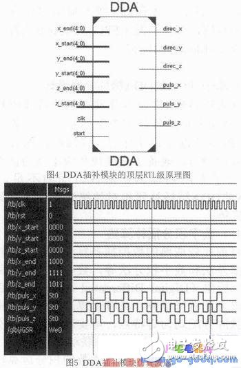
The DDA interpolation module was simulated and verified by ModelSim simulation software. The starting point coordinates of the test data are (0,0,0) and the end point coordinates are (8,15,11). The simulation results are shown in Figure 5. The display system performs the three-axis pulse distribution very well.
4.3 Acceleration and deceleration control module
Acceleration and deceleration control is one of the key technologies of the CNC system, and it is also a bottleneck for realizing the high real-time performance of the CNC system. In the numerical control system, in order to ensure that the machine does not generate impact, out of step, overtravel or oscillation when starting or stopping, the pulse frequency or voltage of the feed motor must be controlled by acceleration and deceleration. That is, when the machine is accelerated, the pulse frequency added to the motor is gradually increased; and when the machine is decelerated and stopped, the pulse frequency applied to the motor is gradually reduced. At present, the common control methods for motor acceleration and deceleration are trapezoidal acceleration and deceleration control and S-shaped acceleration/deceleration control. This design uses two control schemes to suit the requirements of different workplaces.
4.3.1 Trapezoidal acceleration and deceleration
Trapezoidal acceleration/deceleration refers to the acceleration and deceleration process in which the acceleration is constant during acceleration and deceleration and the speed curve is trapezoidal. The trapezoidal acceleration/deceleration control algorithm is simple and easy to implement, but the acceleration curve is not continuous during acceleration and deceleration, which will cause vibration and shock of the drive mechanism. Under normal circumstances, the trapezoidal acceleration and deceleration motion process is divided into three stages: acceleration section, uniform velocity section and deceleration section.
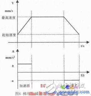
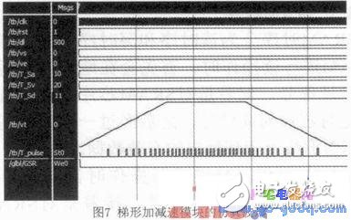
Figure 7 shows the simulation results of ModelSim's trapezoidal acceleration/deceleration module. It can be seen that the pulse speed curve of the interpolator output is trapezoidal, and the frequency of the output pulse changes with the speed, which realizes the trapezoidal speed regulation of the motor.
4.3.2 S-shaped acceleration/deceleration S-shaped acceleration/deceleration refers to the acceleration-deceleration process in which the acceleration derivative is constant and the speed curve is S-shaped curve during acceleration and deceleration. By controlling the acceleration derivative to avoid sudden changes in acceleration, the mechanical system vibration caused by sudden changes in acceleration during processing is reduced. S-curve speed control can obtain a smooth speed curve, but the algorithm is complex and the operation time is long.
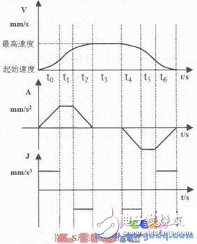
The variation law of the acceleration relative acceleration derivative in S-shaped acceleration and deceleration is equivalent to the variation law of the speed relative acceleration in linear acceleration and deceleration. As shown in Fig. 8, the graph of the S-curve acceleration and deceleration is shown in the figure from top to bottom as the speed curve, the acceleration curve and the deceleration curve. It can be seen from the figure that under normal conditions, the S-shaped acceleration/deceleration is divided into seven stages: acceleration section, uniform acceleration section, deceleration section, uniform section, acceleration/deceleration section, uniform deceleration section and deceleration section. The acceleration is continuous and the speed regulation is smooth, which will not cause vibration and impact of the drive mechanism.
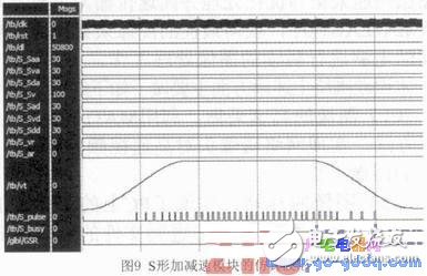
Figure 9 shows the simulation results of ModelSim's S-shaped acceleration/deceleration module. It can be seen that the pulse speed curve of the interpolator output is trapezoidal, and the frequency of the output pulse changes with the speed, which realizes the S-shaped adjustment of the motor. speed.
5 ConclusionThis paper presents an open embedded CNC system based on ARM and FPGA. It breaks through the traditional computer numerical control system architecture and uses ARM processor S3C2440A and FPGA device XC3S25 0E and μC/OS-II embedded real-time operating system. The CNC system software and hardware platform makes full use of the high-speed computing capability of the ARM microprocessor and the fast configuration capability of the FPGA, which greatly reduces the peripheral interface devices of the system, and has good stability, modularity, scalability, and portability. Characteristics such as sex are conducive to the realization of open and networked CNC system, effectively reducing system cost, suitable for the development of CNC systems in China, and have broad application prospects.
The system to realize the automation of liquid level control is composed of hardware and software. The hardware mainly includes PLC touch screen and related CPU, memory, output and input, power supply and other modules. The on-site measurement includes all kinds of sensors and switches suitable for different on-site conditions. In addition, it also includes audible and visual alarm lights, control buttons and other related equipment. By configuring PLC liquid level display alarm instrument, it can realize the display of industrial field liquid level measurement, the alarm of high and low liquid level, as well as the opening and closing of pumps, valves and other equipment. It can realize unattended automatic workflow, greatly improve the production efficiency, save human cost, and bring about the increase of enterprise benefits, Lay the foundation for enterprises to take the lead in the severe competition in the future. Therefore, in the current situation, whether it is a new project or a transformation project, it is suggested that if conditions permit, starting PLC equipment is the priority.
Alarm Box,High Alarm Box,High Alarm Box Device,Level Display Alarm Box
Taizhou Jiabo Instrument Technology Co., Ltd. , https://www.taizhoujbcbyq.com
