Abstract: This application note introduces the design considerations of an ultrasound imaging system, discusses the development trend of miniaturization, low cost, and portability of the imaging system. It also explains the importance of implementing the performance and diagnostic capabilities of large vehicle-mounted systems in small systems. condition. The article discusses the sub-functions of ultrasonic systems and the requirements for electronic components, focusing on sensors, high-voltage multiplexers, high-voltage transmitters, imaging channel receivers, digital beamforming, beamforming digital signal processing, and display processing.
Overview
By transmitting ultrasound energy into the human body, receiving and processing the returned reflected signal, the phased array ultrasound system can generate images of organs and structures in the body, map blood flow and tissue movement, and provide highly accurate blood flow velocity information. In the traditional design, building such an imaging system requires a large number of high-performance phased array transmitters and receivers, making the vehicle-mounted equipment bulky and expensive. In recent years, with the advancement of integration processes, designers have been able to obtain small-sized, low-cost, and highly portable imaging system solutions, and can achieve performance indicators close to large imaging devices. However, new design challenges still exist, that is, to further improve the integration of the solution while improving system performance and diagnostic capabilities.
sensor
The key component of the imaging system is the ultrasonic sensor. A typical ultrasound imaging system requires the use of various sensors to support specific diagnostic requirements. Each sensor consists of a group of piezoelectric sensor cell arrays, which concentrate energy and emit it into the human body, and then receive the corresponding reflected signal. Each unit is connected to the ultrasound system through a thin coaxial cable. Usually, the sensor is composed of 32 to 512 units, and the operating frequency is 1MHz to 15MHz. Most ultrasound systems provide two to four sensor conversion interfaces, and clinicians can easily replace sensors according to different detection types.
High voltage multiplex switch
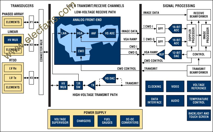
A typical phased array ultrasound system is equipped with 32 to 256 transmitters and receivers. In most cases, the system has fewer transmitters and receivers than sensor units. In these cases, a high-voltage switch needs to be installed in the sensor or system for signal multiplexing. The switch is connected between a specific sensor unit and a transmitter / receiver (Tx / Rx) pair. Thereby, the system can dynamically change the effective sensor aperture in the provided sensor array.
The requirements of the imaging system for high-voltage switches mainly include several aspects: they must be able to withstand the transmission pulses with voltage swings up to 200VP-P and peak currents up to 2A; the switches must be able to switch quickly to quickly adjust the effective aperture and meet the image frame rate Finally, these switches must also have a very small charge injection to avoid spurious transmission and related false images.

Functional block diagram of ultrasound imaging system.
High voltage transmitter
The digital transmit beamformer is used to generate the required digital transmit signal to generate the focused transmit signal at the correct time and phase. High-performance ultrasound systems can generate complex emission waveforms through arbitrary waveform generators, thereby optimizing image quality. In these cases, the transmit beamformer generates 8-bit to 10-bit digital characters at a rate of approximately 40 MHz and uses this to generate the required transmit waveform. A digital-to-analog converter (DAC) converts the digital waveform into an analog signal, which is amplified by a linear high-voltage amplifier and used to drive the sensor unit. Because this type of transmission technology occupies a large volume and is expensive and requires high energy consumption, this architecture is limited to expensive non-portable devices. Most ultrasound systems do not use this transmit beamforming technology, but use a multi-stage high-voltage pulse generator to generate the signal to be transmitted. In this alternative solution, a highly integrated, high-voltage pulse generator is used to quickly switch the sensor unit to an appropriate programmable high-voltage power source to generate a transmission waveform. In order to generate a simple two-pole emission waveform, the pulse generator needs to alternately switch the sensor unit to the positive and negative emission voltages controlled by the digital beamformer. A more complex design allows the sensor unit to switch to multiple power sources and ground, resulting in more complex and better performing multiple waveforms.
In recent years, with the widespread use of second harmonic imaging, the requirements of high voltage pulse generators for slope and symmetry have become higher and higher. Second harmonic imaging uses the nonlinear acoustic characteristics of the human body. These non-linear characteristics tend to convert the sound energy at the frequency fo to the 2fo frequency. Various reasons make it possible to obtain higher image quality when receiving second harmonic signals. Therefore, second harmonic imaging has been widely used.

There are two basic methods of second harmonic imaging. One is called standard harmonic imaging, which suppresses the second harmonic of the transmitted signal as much as possible, so that the received second harmonic mainly originates from the nonlinearity of the human body. This mode requires that the emission energy of the second harmonic is at least 50dB lower than the fundamental energy. Therefore, the duty cycle of the transmitted pulse is required to be 50% accurate and the error is less than ± 0.2%. Another method is called pulse inversion, which uses inverted transmission pulses to generate two received signals with opposite phases in the same image path. In the receiver, the two inverted received signals are summed to restore the harmonic signal due to the nonlinearity of the human body. This method of pulse inversion must counteract the inverted component of the transmitted pulse as much as possible during superposition. Therefore, the rise time and fall time of the high-voltage pulse generator must be strictly consistent.
Imaging channel receiver
The receiver of the ultrasound imaging channel is used to detect two-dimensional (2D) signals and pulsed Doppler (PWD) signals and spectrum PWD required for color Doppler fluid imaging. The receiver includes a Tx / Rx switch, a low noise amplifier (LNA), a variable gain amplifier (VGA), an anti-aliasing filter (AAF), and an analog-to-digital converter (ADC).
Tx / Rx switch
The Tx / Rx switch protects the low-noise amplifier from high-voltage transmit pulses, while isolating the low-noise amplifier input from the transmitter during the reception interval. The switch is generally implemented with a set of correctly biased diode arrays. When a high-voltage transmit pulse occurs, they will automatically close or open. The Tx / Rx switch must have a fast recovery time to ensure that the receiver can be turned on immediately after transmitting a pulse. These fast recovery times are critical for shallow buried imaging and providing low on-resistance to ensure receiving sensitivity.
Low noise amplifier (LNA)
The LNA in the receiver must have excellent noise performance and sufficient gain. For a properly designed receiver, the LNA will determine the noise performance of the entire receiver. The sensor unit is connected to the input of the corresponding low-impedance LNA via a long coaxial cable. Without proper cable termination matching, the cable capacitance and the source impedance of the sensor unit will greatly limit the bandwidth of the signal received from the broadband sensor. The sensor cable is matched to a low resistance, which helps to reduce the impact of this filtering and effectively improve the image quality. Unfortunately, this termination also reduces the input signal of the LNA, thus reducing the receiving sensitivity. This shows that it is very important to provide active input termination for the LNA, which can provide the necessary low input impedance termination and excellent noise performance under the above conditions.

Variable gain amplifier (VGA)
VGA is sometimes referred to as a time gain control (TGC) amplifier, which can provide sufficient dynamic range for the receiver during the entire receiving cycle. Ultrasound signals are transmitted approximately 1540 meters per second in the body, and the round-trip attenuation rate is 1.4dB / cm-MHz. After transmitting an ultrasonic pulse, an echo signal of up to 0.5VP-P can be received at the LNA input, and the signal will quickly fall to the thermal noise floor of the sensor unit. The dynamic range required to receive this signal is approximately 100dB to 110dB, which exceeds the input range of the actual ADC. Therefore, it is necessary to use VGA to convert the signal into a signal amplitude equivalent to the ADC range. A 12-bit ADC is used in a typical application, and VGA is required to provide a gain of 30dB to 40dB. The gain is adjusted with time (ie "time gain control") to achieve the required dynamic range.
The transient dynamic range of the ultrasound receiver is also very important, it will affect the quality of the 2D image and the system's ability to detect Doppler shift (blood or tissue movement), especially in the second harmonic imaging system. The second harmonic signal is significantly lower than the fundamental wave of the transmitted signal. The same is true for small Doppler signals. The frequency of the Doppler signal may be within 1 kHz, and the amplitude is much lower than the reflected signal of the tissue or blood vessel wall. Therefore, special attention needs to be paid to the bandwidth of the variable gain amplifier and the near-carrier SNR. These parameters are usually the key to restrict the performance of the receiver.
Anti-aliasing filter (AAF) and ADC
The anti-aliasing filter AAF is placed in the receiving channel to filter out high-frequency noise and signals that exceed the normal maximum imaging frequency range to prevent these signals from being aliased by the ADC to baseband. Most of the design uses adjustable AAF. In order to suppress aliasing and ensure the time-domain response of the signal, the filter needs to attenuate the signal beyond the first Nyquist frequency. Therefore, Butterworth filters or higher order Bessel filters are often used.
A 12-bit ADC is used in a typical application, and the sampling rate is usually between 40Msps and 60Msps. The ADC provides the necessary transient dynamic response range while having the appropriate cost and power consumption. In a properly designed receiver, the ADC limits the transient SNR of the receiving channel. As mentioned above, poor performance VGA will limit the SNR index of the entire receiving channel.
Digital beamformer
The output signal of the ADC is transmitted to the digital receiving beamformer through the high-speed LVDS serial port. This transmission method reduces the design complexity of the PCB and the number of interface pins. The beamformer has a built-in up-conversion low-pass filter or bandpass digital filter. These filters increase the effective sampling rate by a factor of four and improve the accuracy of the system's beamforming. The up-converted signal is stored in the memory, and after an appropriate delay, it is superimposed by a delay coefficient adder to obtain an appropriate focus. The signal is also appropriately weighted or "apodized", and apodization is performed before superposition, which can adjust the receiving aperture, reduce the influence of side lobes on the receiving beam, and improve image quality.
Digital signal processing for beamforming
The received beamforming digital ultrasonic signals are processed by DSP and PC-based devices to obtain video and audio output signals. This process can usually be divided into B-mode or 2D image processing, and Doppler processing with color Doppler fluid imaging information. Doppler processing is further divided into pulse Doppler (PWD) processing and continuous wave Doppler (CWD) processing. .
B ultrasound processing
In B-mode ultrasound processing, the RF beamforming digital signal is filtered and detected. The detection signal has a very wide dynamic range, and the B-mode processor must digitally compress these signals to achieve the dynamic range specified by the display.
Color ultrasound fluid signal processing
In color Doppler fluid signal processing, the RF digital beamforming signal is mixed with the orthogonal local oscillator signal (LO, the frequency is the transmit frequency) to obtain I and Q baseband signals. The ultrasonic signals collected by each receiving channel have corresponding amplitude and phase. In color Doppler fluid signal processing, 8 to 16 ultrasound signals are concentrated in one imaging channel to measure the Doppler frequency shift. The reflected signal generated by blood flow or tissue movement along the imaging channel has a certain Doppler frequency shift, thereby changing the phase of the I / Q baseband sampling signal. The color Doppler fluid processor determines the average phase shift and time relationship of the 8 to 16 ultrasound signals of the imaging channel. The processor also represents the average flow rate in color. In this way, two-dimensional contrast imaging of blood or human tissue movement is achieved.
Doppler spectrum
In spectrum processing, the beamforming digital signal is digitally filtered and mixed to the baseband signal by the orthogonal local oscillator signal (LO, the frequency is the transmit frequency), and then sampled at the transmit pulse repetition frequency (PRF). The complex fast Fourier transform (FFT) is used to obtain the Doppler spectrum to reproduce the speed information of the received signal. The amplitude of each binary signal output by the FFT is calculated and compressed so that it reaches the dynamic range required for displaying the image. The final signal amplitude is displayed on the display of the ultrasound device as a function of time.
In continuous wave Doppler (CWD) imaging system, the signal processing process is basically the same. In addition to processing these display signals, the spectrum processor also produces stereo audio signals for the left and right channels, indicating positive and negative motion. The DAC converts these signals to drive external speakers and headphones.
Display processing
The display processor performs the necessary calculations and draws a polar plot. The sound, image data or color Doppler fluid information in B-mode ultrasound is processed into a rectangular bitmap, thereby eliminating spurious signals in the image. This process is commonly referred to as R-θ transformation, and the display processor also provides spatial image enhancement.
Continuous wave Doppler (CWD)
In most cardiac examinations and some general ultrasound imaging systems, continuous wave Doppler CWD is often used to ensure accurate measurement of high-speed blood flowing in the heart. In CWD mode, the ultrasonic sensor unit is divided into two equal parts centered on the sensor aperture. One half of the unit is used for transmission and generates a CWD focused beam; the other half is used for reception and generates a focused receive beam. The driving waveform of the transmitting unit is a square wave of Doppler frequency, and the frequency range is usually 1 MHz to 7.5 MHz. The jitter of the transmitted waveform must be small enough to prevent the influence of phase noise on Doppler shift detection. By correctly adjusting the phase of the transmission waveform, the transmission beam is focused. Similarly, by correctly adjusting the phase of the received waveform and superimposing it, the CWD received signal is focused. In this mode, the transmission and reception are carried out at the same time, the useful Doppler signal frequency and the frequency of the strong reflection signal generated by the non-moving human tissue at the fundamental frequency of the transmission are only a few kHz. The dynamic range required to process such a large signal has exceeded the range that the image receiving channels VGA, AAF and 12-bit ADC can withstand. Therefore, CWD must use other high dynamic range reception solutions.
CWD receivers generally use two methods to process CWD signals. The first method is that the high-performance ultrasound system extracts the received CWD signal at the output of the LNA. A mixer whose local oscillator frequency is equal to the transmission frequency beamforms the signal, and then mixes it to baseband for processing. The I / Q local oscillator signal can adjust the phase channel by channel and shift the phase of the received CWD signal. The mixer outputs are superimposed, pass the band-pass filter, and finally enter the ADC for sampling. The sampled baseband beam signal is in the audio frequency range (100 Hz to 50 kHz), and the ADC working in the audio frequency range is used to digitize the I and Q CWD signals. These ADCs require excellent dynamic range in order to process large low-frequency Doppler signals generated by moving tissues and weak signals generated by blood.
Another method is to use a delay line to receive the CWD signal. This method is often used in low-cost devices. In this method, the signal is still extracted from the LNA output and then converted into a current signal. The channels of the same phase are superimposed through a crossbar to produce 8 to 16 independent outputs, which are determined by the receiving beamformer. The delay line produces a delay, and these signals are summed to form a beamforming RF signal, and then an I / Q mixer whose local oscillator frequency is equal to the transmission frequency is used to mix the signal to baseband, and then the baseband audio signal is filtered and converted To digital form.
Auto spare lamp kits are extra lamp pieces that can be used to replace a piece that broken. There are many different bulbs and fuses in one spare lamp kits. For example, there are one H4 for headlight, one S25 singe filament for signal light, one dual filament S25 for stop light, one G18.5 for truck light or license plate light, one T10 for interior light or side indicators light and two different types of fuses that can replace the burned fuse. The customers will review what specs their own vehicle have and choose which to buy. Having a spare lamp in the car is like buy a insurance, because every light on the car has its specific purpose, which means any broken bulb might put the driver and others in a very dangerous situation. Highly recommend have one kits in the car.
Auto Spare Lamp Kits
Auto Spare Lamp Kits,Auto Bulb Halogen Parking Lamps,Car LED Auto Light,Super White Headlight
Heshan Jianhao Lighting Industrial Co., Ltd. , https://www.sunclubtw.com
