A digital water temperature preparation valve based on PIC16C71 microcontroller is designed. The preparation valve adopts an NTC thermistor as a temperature sensor, and a simple voltage dividing circuit composed of a fixed resistor as a water temperature measuring circuit, and converts the analog voltage on the thermistor into a digital quantity by using an 8-bit A/D converter built in the PIC16C71 single-chip microcomputer. PIC16C71 MCU controls the DC motor drive mixing valve to adjust the mixing ratio of hot and cold water to achieve water temperature adjustment. The control circuit diagram is given, and the parameter selection and temperature measurement accuracy of the water temperature measurement circuit are discussed in detail. Experiments and analysis show that the selection of NTC thermistors and voltage divider resistors with large resistance values ​​can better solve the thermal breakdown problem caused by the large power consumption of the thermistors.
With the development of society, various water heaters and pipeline hot waters have entered thousands of households. People have different water temperature requirements in different occasions. It is often necessary to mix hot water and cold water to the required temperature. It can control the water temperature of various water heaters and pipeline hot water, and can quickly and accurately prepare the hot water of the required temperature. It can be used for shower, washing and other water temperature intelligent preparation valves that require constant temperature hot water. It is an application value. technology. This design is in line with this need, with the PIC16C71 chip as the core, the control mechanical part automatically adjusts the mixing ratio of cold water and hot water, realizes the automatic control of the outlet water temperature, and solves the problem caused by water pressure fluctuation, water temperature change or water output change. The problem of the water temperature being cold and hot is obviously more water-saving than the manual adjustment of the water temperature.
1 system structure and working principle
Hot water and tap water are used as the two inputs of the control valve. The mixing valve is used to control the input and proportion of the cold and hot water. The mixed water flows out through the water outlet for the user to use. A temperature sensor installed at the water outlet senses the temperature at the water outlet and transmits it to the microcontroller through the temperature measuring circuit. The composition of the temperature control water valve is shown in Figure 1. When the water outlet switch is turned on, the single-chip microcomputer compares the temperature at the water outlet measured by the temperature sensor with the set temperature. When necessary, the PIC16C71 controls the DC motor to drive the mixing valve to adjust the proportion of cold water and hot water entering the water valve. Thereby controlling the temperature of the water outlet, when the motor is turned to the head, the single-chip microcomputer obtains a corresponding signal, and terminates the motor to continue to rotate in the same direction. The water temperature is set in the range of 25 to 50 °C by the temperature rise or temperature drop button, and the LED digital tube displays the set water temperature value. If the set temperature does not match the temperature detected by the sensor, according to the temperature difference between the two, the single chip outputs different pulse voltage signals to control the DC motor to rotate at different speeds, drive the hot and cold water mixing valve through the transmission mechanism, and change the cold water and hot water. Inflow ratio. When the external conditions change again, such as the water pressure decreases or increases, the temperature difference between the outlet water temperature and the set temperature occurs. At this time, the MCU once again controls the motor rotation to automatically adjust the water temperature to automatically set the water temperature of the outlet. The water temperature is kept the same.

2 control panel and circuit
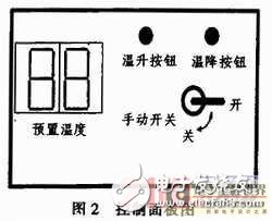
Design control panel buttons should be minimized, easy to use, reasonable in function, easy to control, and the meter can display the set temperature. The control panel is shown in Figure 2. The 2-digit LED digital tube on the left side of the panel is used to display the preset water temperature. The temperature rise button and the temperature drop button on the upper right side of the panel are used to increase and decrease the temperature of the preset water temperature. The lower right of the panel is a manual switch, which determines the size of the water valve's switch and water output. When it is placed “offâ€, it is closed to the non-working state.

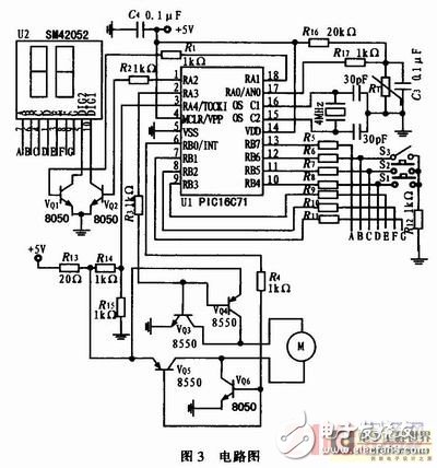
Figure 3 is a circuit diagram of a control valve. The system uses a low-voltage DC power supply, uses the PIC16C71 microcontroller to control, and implements various functions through program control.

2.1 Temperature measurement principle and parameter selection
In Fig. 3, the thermistor RT is a temperature measuring element for measuring the water temperature at the water outlet. A fixed resistor R16 is connected in series with the thermal RT to form a voltage divider circuit. The voltage drop across the RT is connected to the pin through the resistor R17 to the AN0 input to the PIC16C71's built-in 8-bit A/D converter to convert the analog voltage signal into a digital The signal is read by the program to achieve temperature measurement. The key to temperature measurement is to choose the appropriate temperature measuring components and reasonable circuit parameters. The choice here is a negative temperature coefficient thermistor (NTC), which is packaged in a glass envelope, small in size, low in price, and easy to install. The main advantages of NTC temperature-sensing thermistor are large temperature coefficient of resistance, high sensitivity, fast response, and accurate temperature measurement. The main disadvantage is that the nonlinearity of thermoelectric characteristics is serious. If using C408503 (50 kΩ at 25 °C, B value 4 050 K, glass package) NTC thermistor, the sensitivity of the resistor is about 8 500 ~ 100 Ω / ° C in the range of 0 ~ 99 ° C, nonlinear Serious, linear compensation is generally required when using. Here, through calculation, the reasonable temperature measurement circuit parameters are selected. In the effective temperature measurement range, no linear compensation is performed, and the nonlinear problem of the NTC temperature measurement resistance is effectively solved by only using the temperature look-up table. The selection of temperature measurement accuracy and circuit parameters will be discussed below.
The resistor R16 and the thermistor RT are connected in series to form a voltage dividing circuit, which divides the power supply voltage by 5 V, and the voltage drop on the RT Vi=5 V·RT/(RT+R16) changes with temperature. This voltage is fed to the A/D converter inside the PIC16C71 through the A/D input pin AN0, converted to a digital signal, and read by the program. A 0.1 μF capacitor C3 is connected to the RT for filtering to eliminate interference and noise. In the trial, it was found that when the selected NTC thermistor (such as nominal 10 kΩ) and the voltage divider resistor (such as 5.1 kΩ) have a small resistance value, the thermistor is easily broken down after working for a while, and After selecting the NTC thermistor and the voltage dividing resistor with large resistance, the problem is solved. The reason for the analysis should be the thermal breakdown caused by the large operating current and power consumption in the NTC thermistor. Therefore, NTC thermistors and voltage divider resistors with large resistance should be used as much as possible to minimize the current flowing through the thermistor. On the other hand, considering that the input leakage current of the A/D input signal pin of the PIC microcontroller is at most ±500 nA, to ensure the correct A/D conversion result, the voltage on the internal resistance of the signal source must not exceed 10 mV. (The A/D reference voltage is 1/2 LSB at 5 V), which requires the signal source internal resistance to be no more than 20 kΩ. When an NTC thermistor with a nominal 50 kΩ and a B25/50 of 4 050 K is used, its resistance in the temperature range (0 to 99 °C) varies between 168.3 and 3.217 kΩ. When the fixed divider resistor is selected to be 20 kΩ, the equivalent internal resistance of the A/D input signal source is the resistance of the thermistor and the divider resistor in parallel.
For diifferent USB types, micro USB, mini USB, etc. The logo, color or shape can all made as customers' requirement. With more than ten years of experience and capabilities assisting our customers in various industry, ETOP would be confident to be your qualified AVL and reliable manufacturing partner.
Related Products:usb cable,micro usb cable,usb data cable.
Data Cable,Data Flexible Electrical Magnetic Cable,Usb Data Cable,Micro Usb Cable,USB Connector
ETOP WIREHARNESS LIMITED , https://www.wireharnessetop.com
