Boost circuit not only can boost, but also requires less components in the topology itself, which is beneficial to improve efficiency, and is very suitable for applications that need to supply batteries to LEDs. Analog dimming and digital dimming of LEDs is achieved through the application of innovations to the controller LTC3783. And the system is designed to work properly for LED arrays with power ranging from a few watts to tens of watts, batteries with terminal voltages ranging from 6-36V, and maintenance of the product - the need to replace the LED or when the battery needs to be replaced, As long as the above requirements are met, the system can operate normally and stably without replacing the circuit module.
Foreword
Due to its high luminous efficiency, high reliability, long life and other advantages, light-emitting diodes (LEDs) are widely used in lighting, signal display, imaging and other fields, and are widely regarded as a traditional light source that replaces incandescent lamps and fluorescent lamps. New light source.
There are many ways to drive an LED, and the easiest way is to connect the LED in series with the current limiting resistor and then supply it from a voltage source. The advantage of this type of drive is that the circuit is simple, but there are also many drawbacks. The first is low efficiency, the step-down resistor consumes a lot of power, and may even exceed the power consumed by the LED. Secondly, the stable voltage capability is extremely poor, and the VI curve of the LED has a negative temperature characteristic. As the junction temperature increases, the flow The current through the LED will be larger and larger. Therefore, if the drive current is not controlled, the LED is easily burned, and even if it is not burned, the life will be greatly shortened. Therefore, current control is required when driving high power LEDs. In addition, the illuminance of the LED light source is directly related to the current, so the illumination current of the LED is controlled and the illuminance is also controlled.
1 system design
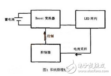
The principle block diagram of the system is shown in Figure 1. The power supply is a lead-acid battery, and the load is an array of LEDs. The LTC3783 is used as a controller to implement PWM control. This circuit is designed to simulate dimming and digital dimming of LEDs simultaneously. And the system can work normally for LED arrays with power ranging from a few watts to tens of watts, and batteries with terminal voltages ranging from 6-36v, so that when the product is to be repaired - when the LED needs to be replaced or the battery needs to be replaced, as long as it is satisfied The above requirements, the system can work normally and stably without replacing the circuit module.

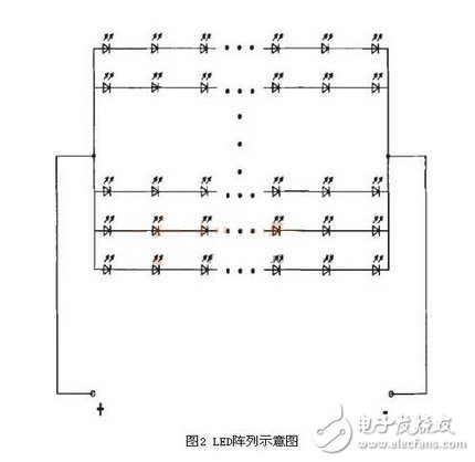
Due to various limitations such as heat generation and heat dissipation technology, the power of a single LED cannot be made as large as a conventional light source. A LED with a power of 1w is a high-power LED. In practical applications, an array of multiple low-power LEDs is usually used to meet higher illumination requirements and achieve low cost, as shown in FIG. 2 .

There are another significant advantages to using LED arrays. We know that LEDs may be shorted and broken due to certain faults. When a string, the LED in the branch branch is short-circuited, the other LEDs in the branch can still work normally. Although the current through the LED may rise, due to the large number of LEDs, the rising current is not large, and the rising current does not exceed the allowable operating range of the LED. When an LED in a series branch is broken, the string of LEDs is extinguished.
However, since the array is composed of a plurality of LED strings, the other LED strings can still work, and share the current in the extinguished LED string, but since the LED has more branches, the rising current is not large, and the rising current does not exceed The working range allowed by the LED. Therefore, it is obvious that the LED array has relatively higher stability and reliability. 1. Moreover, for a certain number of LED arrays, when the number of branches and the number of LEDs in the branch are matched, it will be more advantageous to enhance the LED. Reliability and stability of component operation.
In the experiment, an array of 8 strings of 20 LEDs per string and an array of 12 strings of 12 LEDs per string were fabricated. The LED used is an O.1w bullet-shaped LED with a rated forward voltage drop range of 3.0-3.3V and a rated forward current range of 10-30 mA. The LED design is operated at 20 mA in the experiment, which can reduce heat dissipation. And there is enough current margin when the LED has a short circuit fault.
HIFU Piezoelectric Ceramic Parts
High Intensity Focused Ultrasound (HIFU) technology is to focus ultrasound on a single point to produce high energy, function on the dermis and SMAS layer of skin, stimulate the proliferation and recombination of collagen, effectively achieve the effect of compact contour and smoothing lines.
Focused ultrasound does not heat the skin surface, nor does it need to pass through the skin as a medium for the transmission of laser energy, so it does not affect the tissue on the skin surface and the tissue through which the laser passes, of course, there will be no excessive heat residue on the skin surface. In this way, the epidermis will not be affected by heat, which can reduce the Eastern people's thermal reaction easily, and greatly reduce the chance of scald. Focused ultrasoundtherapy produces thermal coagulation points in the SMAS layer, and the thermal effect diffuses outward from the coagulation points, so the heat source is concentrated in the SMAS layer to be treated. It can produce more collagen denaturation.
Ultrasonic Transducer Component,Piezo Crystal For Vibration Transducer,Piezoelectric Ultrasonic Rings,High Power Ultrasonic Machining
Zibo Yuhai Electronic Ceramic Co., Ltd. , https://www.yhpiezo.com
