1 Introduction
The car door lock has many types and specifications, large structural differences, many inspection items, and some structures are loose and easy to deform. The automobile door lock assembly inspection production line requires fast detection speed, low failure rate, and allows product detection content to have certain expansion. .
This article refers to the address: http://
In the past, most of the methods used to decompose the detection items into separate sub-stations were used, which often caused defects in the structure of the sub-station equipment, cumbersome operation, long equipment design cycle, high failure rate, and loose and unsuitable contact with the car lock structure. The inspection relies on manual visual inspection. Not only is the operator labor-intensive, but also due to artificial factors, it is prone to error.
With the development of industrial production, the manufacturing level of automation equipment is also increasing, and the introduction of machine vision (hereinafter referred to as visual) system has solved these problems well.
2 Introduction to Visual Technology
Vision technology is to use the machine instead of the human eye to make measurements and judgments. It takes images through the lens (Camer a) and converts the distribution of pixels, brightness, color and other information into digital signals; the image system operates on these signals to extract The characteristics of the image, and on this basis, implement pattern recognition, coordinate calculation, grayscale distribution and other functions, thereby performing logical judgments to control the field device.
Machine vision inspection has the following advantages over manual inspection.
3 visual system design
3.1 Hardware part design
(1) Image acquisition part: lens PULNix TM-200, Cognex image acquisition card (can connect 4 groups of lenses); (2) image processing part: PC (DELL GX5200); (3) electromechanical control part: SeaIO I/O Card (PCI slot), control cabinet (built-in air switch, terminal block, etc.) constitutes the electrical control system; (4) Electromechanical actuator: button, sensor, cylinder, valve terminal, indicator light, buzzer, etc.; (5) Human-computer interaction part: display, mouse, keyboard.
3.2 Software part design
Based on Cognex's visual analysis tools, the project developed a visual operating platform.
(1) Software environment for system development.
Windows 2000 or Windows XP or higher; Office 2000 or above; VisiONPro 50 or above; SeaIO_v030103 or above; VS2005TF.
(2) Requirements for software development.
The car door lock has many detection points (in this case, a total of 23 points), and the variety of features, which requires the software to freely combine the detection points into each variety, and the operation interface is as simple and easy to operate as possible.
(3) The function of the software.
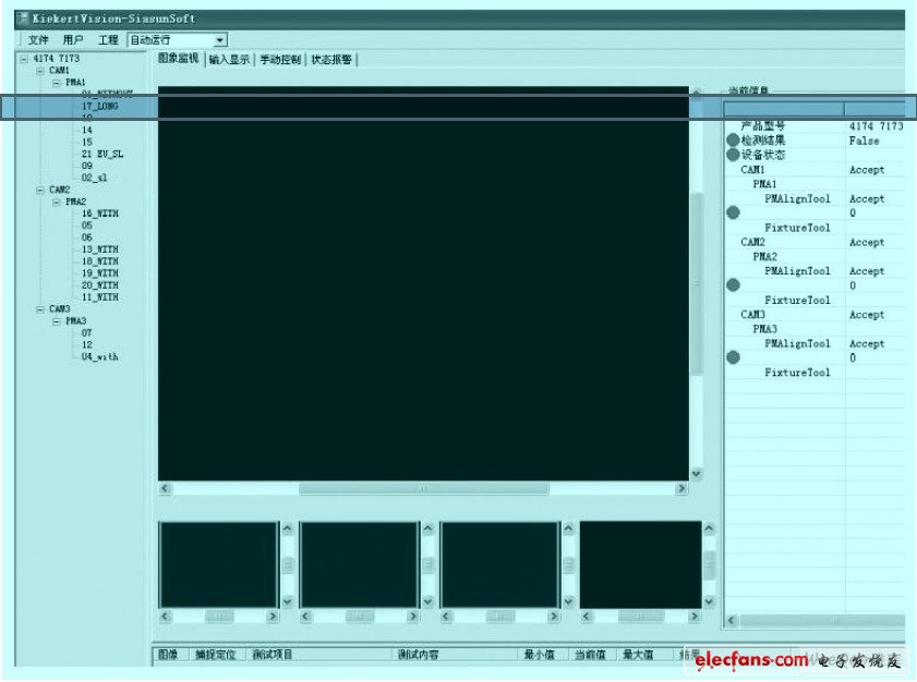
Figure 1 main interface
The main interface of the software is shown in the figure. The left side shows the model of the current lock, the selected lens, the positioning origin used, and an overview of the detected points. The right side is rough information such as test results and device status. The upper part of the middle part is the actual image detected by the system. The qualified one is circled with a green border, the unqualified one is circled with a red border, and the text name of the detected point is provided. The image will be displayed by default as containing images with unqualified detection points in the test results. There are four small display areas on the underside of this image, corresponding to different cameras in the system. If the image contains a defective point, the outside of the image will be circled with a red border. The bottom side is the detailed information of each detection point. As shown in Figure 1.
In addition, there are "Input Display", "Manual Control" and "Status Alarm" property pages in the main window. The "Model Selection", "Camera", "PMAlignFixture", "Tools" "Type", "Visual Run" options are added to the menu "Project". as shown in picture 2.
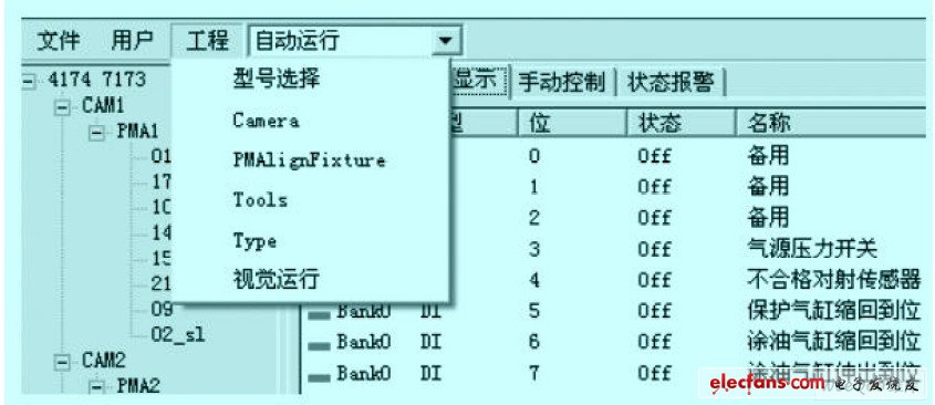
Figure 2 Project submenu.
Software In order to reduce the debugging workload, each measured point can be configured in different visual analysis tools. If each inspection tool contains only one detection point, then when setting the detection content of each model, only need to select for each model. Corresponding detection items can be used, which greatly improves the efficiency of visual debugging. As shown in Figure 3.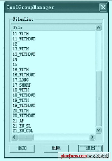
Figure 3: Tool for the detection point (Tools) interface
The software is now applied to Changshu Kieker t car door lock company, which is stable in operation and simple in operation, and can meet various requirements in production and debugging.
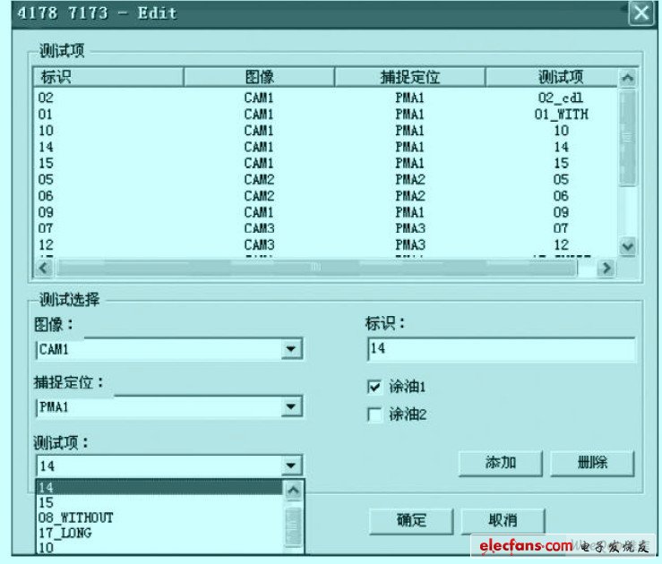
Figure 4 shows the interface for assigning detection items to each model.
4 Application of visual technology in door lock detection
The successful application of a visual system is not only inseparable from the design of the software, but also depends on the rational use of visual analysis tools. For different detection objects to be specifically analyzed, take different detection programs. The following is an example of a common problem in car door lock detection.
4.1 Detecting black objects against a dark background
Visual inspection is essentially the detection of pixel chrominance. The closer the chromaticity of the detected object is to the chromaticity of the surrounding background, the more difficult the detection. For this reason, it is conceivable to use a single lens for the object to be detected, and then enhance the illumination to obtain sufficient gradation. Then consider using the CogPMAlignTool tool in the Cognex Visual Analysis Tool for analysis. This is a tool for finding similar objects in a settable area. First, find the portion of the object to be detected that has a distinct feature and has a large background color difference with it, set it as the object to be detected, and then delineate the searchable area containing the object to be detected. After the similarity is set, the detected object is removed, and the workpiece is detected to obtain a similarity detection value when the detected object does not exist. The threshold value is reset according to the difference between the similarity value when the object exists and the detected similarity value when the object does not exist.
4.2 Detecting objects such as springs that are subject to variable color
The spring-like object is characterized in that the surface color is susceptible to the distribution of the grease, the inclination angle, and the like, thereby forming an image having a large difference in color observed by the human eye. For this, consider using the CogPMAl ignTool tool in the Cognex visual analysis tool to analyze the image.
The setting method is the same as above. Because the similarity is not only reflected in the chromaticity, but also reflected in the shape, this tool can be used to better identify the detected objects.4.3 Small detection point detection
Small detection points tend to be less prominent in shape, and there are fewer corresponding pixels. When searching with the similarity tool, it is easy to misjudge because there are too few feature pixels. Therefore, the CogBlobTool tool in the Cognex visual analysis tool can be used for analysis. This is a tool for finding the presence of an object in a particular area by setting the difference value of the chromaticity. Select mode in Segmentation as Hard Threshold (Fixed), Polarity as LightBlobs, Dark background or Dark Blobs, Light background, then set the detection area, click the dynamic run button, adjust the value of Thr eshold, and observe the right window. The change in the detected condition of the test object. The object to be detected is removed, and the workpiece is detected to obtain a Blob detection value when the detected object does not exist. Re-adjust the blob setting based on the difference between the Blob value when the object is present and the detected Blob value when the object does not exist.
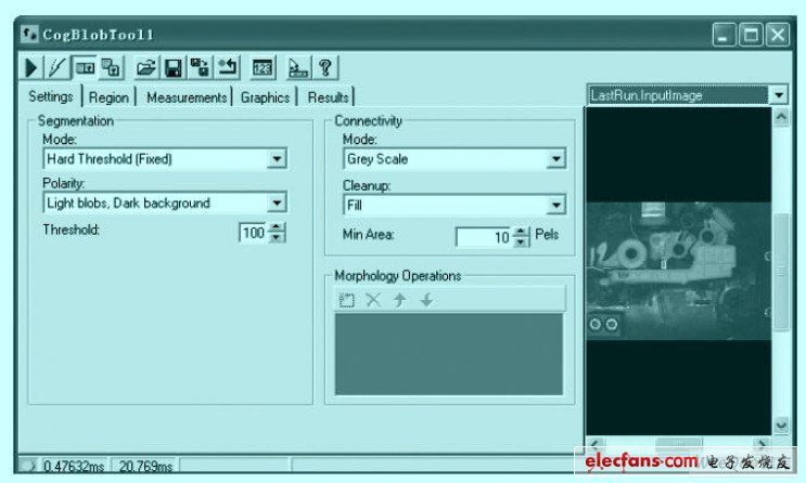
Figure 5 CogBlobTool tool settings interface
4.4 Oily riveting point detection
Due to different working conditions, the surface of some riveting points will have a certain degree of oil stain. This makes visual inspection extremely susceptible to interference. The CogFindCircleTool tool in the Cognex visual analysis tool can be used for analysis.
This is a tool for finding circles and measuring circles in selected areas.
In the Caliper Settings option, the Edge Polarity option should be checked for Any Polarity, as the Dark to Light and Light to Dark options have higher false positives due to oil contamination, while An y Pola ri ty is a set circle. The arc is the benchmark and is judged by the color difference. Therefore, the accuracy is high. In addition, in the Search Direction option, the selection of Inward and Outward should be based on the measured results. If the rivet is a regular cylindrical shape, you can select Inward because the unstudded rivet is often free of oil and has a small radius. When the rivet is star-shaped, the Outward should be selected so that the riveted radius value of the rivet can be accurately determined. . It should be noted that the Number of Calipers in the Caliper option should be selected to be larger according to the size of the circle, so that the circle is judged more fully and the obtained circle is more accurate.
4.5 Detection of objects with variable range
The position of some objects is not fixed, but is randomly present in a certain area, which means that a suitable search area must be selected. To do this, consider using the CogPMAlignTool tool in the Cognex Visual Analysis Tool for analysis. The tool provides a variety of border marking tools, making the setting of the border very user-friendly.
4.6 Hole detection
The detection of through holes on black objects often fails because the chromatic aberration is too close. However, if you add a brightly colored observation to the inspection fixture, pass it through the through hole, and then use the CogBlobTool tool in the Cog nex visual analysis tool for analysis, the problem can be solved.
4.7 Discriminating the fixed area with high or high darkness
It is a common method to distinguish whether an object is bright or dark to distinguish between objects. This can be achieved by setting the CogBlobTool tool in the Cognex visual analysis tool. In addition, the equipment should be designed with full consideration of the process problems of the product. The surface of some of the detectors can be changed by the process of the product, which also provides a new idea for solving the problem.
5 Conclusion
The visual system can quickly and accurately detect the presence or absence of an object without touching the object. In particular, the number of detection points is relatively large and the distribution is relatively concentrated. Depending on the model, there are many types of objects to be detected at the same position. In complex situations, the advantages of visual inspection are more prominent. Of course, the application of the vision system is also limited by factors such as cost, reflectivity of the object to be inspected, and the like. Therefore, flexible and reasonable debugging of the visual system to make it play its biggest role remains to be seen by the industry.
Cast Iron LV 3PH Asynchronous Motor
Cast Iron Lv 3Ph Asynchronous Motor,Three Phase Asynchronous Cast Iron Motors,Cast Iron Motors,Cast Iron Electric Motor
Yizheng Beide Material Co., Ltd. , https://www.beidevendor.com
