1 Overview
my country is a big agricultural country. At present, there are more and more agricultural greenhouses in the vast rural areas. In recent years, with the development of my country's agriculture and rural economy, the mode of agricultural production has gradually changed from the traditional extensive management type to the modern intensive management mode. and live. With the advancement of science and technology, the structural grade of greenhouses is gradually improving. The construction of a greenhouse intelligent monitoring system that can improve the yield and quality of crops in the greenhouse, reduce production costs, and reduce the labor intensity of staff is an important task for the majority of greenhouse crop producers. Urgent needs.
The agricultural greenhouse intelligent monitoring system collects the air temperature, humidity, light, soil temperature, soil moisture and other environmental parameters in the agricultural greenhouse in real time, makes real-time intelligent decision-making according to the needs of crop growth, and automatically turns on or off the designated environmental adjustment equipment. Through the deployment and implementation of the system, it can provide scientific basis and effective means for automatic monitoring of agricultural ecological information, automatic control of facilities and intelligent management.
2. Features
â‘ Realize the collection of soil temperature, air temperature, humidity, light, carbon dioxide, soil moisture and other information;
â‘¡KL-H1100 IoT gateway is used as a data receiver and collector, with Ethernet and 3G dual communication, easy to upload data
â‘¢ZigBee intelligent self-organizing network mechanism, using 2.4GHz frequency communication, long transmission distance and strong penetration;
â‘£Battery, mains, solar power supply methods, the sensor layout is not limited by the power supply;
⑤Stable wired transmission control, free control of rolling shutter machines, skylights and other equipment;
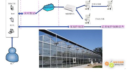
2 specific implementation plans
1 Overview
This example is the Tianjin greenhouse monitoring system. There are 13 ordinary sunshades here, each with 240 solid walls in the east-west direction, south-facing steel frame structure, and covered with plastic film. The greenhouse is mainly for planting vegetables, mainly realizes data monitoring, and reasonably controls the roller shutter system and drip irrigation system according to the data. Realize modern agricultural planting, save manpower and increase efficiency.
2. On-site environment
The 13 greenhouses are arranged in two rows. As shown in the figure, each greenhouse is 10 meters long and 5 meters wide. The center of No. 1 and No. 2 greenhouses are separated by 10 meters, and the two rows of greenhouses are separated by 6 meters. Because the greenhouse environment is good and the AC 220V power supply is sufficient, all sensors use routing devices. The advantage of routing is that the connection between the sensor and the IoT gateway is more convenient and the network is better. The disadvantage is that there is no sleep function, and there must be an external power supply.
3. Main equipment
â‘ KL-H1100 IoT gateway 1 piece
â‘¡ JZH-026-12 13 wireless sensors for temperature, humidity, soil temperature, soil moisture, carbon dioxide
â‘¢ 13 JZH-002-12 illuminance wireless sensors
â‘£ 3 JZH-000-12 empty node routing sensors
⑤ Several environmental protection boxes
Note: The sensors are all routing sensors
4. Layout plan
â‘ Put the KL-H1100 IoT Gateway in the receiving box on the billboard.
â‘¡ The JZH-002-12 and JZH-026-12 wireless sensors 2 are only one group and placed in 13 greenhouses respectively.
â‘¢ Put the JZH-000-12 empty node routing sensor in the protective box at the top of the greenhouse on No. 7, No. 9, and No. 11.
5. Hardware installation
①In the center of the greenhouse, a 6-point or 4-point steel pipe needs to be erected from the ground to the roof. There is a 220VAC power socket and a 400×400mm flat plate 2 meters from the ground to install the sensor. The plate is punched with two holes in the center with a diameter of 5.3mm. The schematic diagram of the sensor size hole is as follows:
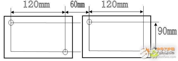
②For outdoor use, 3 iron boxes (protective boxes) of 300mm×300mm are required. There is a 220VAC power socket inside, and there is a through hole on the side that is 1/3 away from the upper part, with a diameter of 7mm. It is used to connect to the antenna. The opening size of the inner plate is shown in the figure above, and the wireless sensor is fixed. They are installed above the 7th, 9th and 11th sheds respectively.
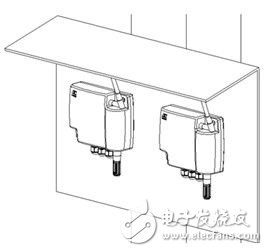
③A 300mm×300mm protective box is also required above the billboard position, with a 220VAC power socket inside, and a through hole on the side 1/3 from the upper part with a diameter of 7mm, which is used to connect to the antenna. Two holes with a size of Φ4 and a spacing of 110cm are required in the middle and upper part of the inner plate, which are used to penetrate screws and hang the gateway.
â‘£ Install the device to the designated location.
6. Protection of equipment
In practical applications, since the gateway and sensor are not completely sealed, a protective box is required to protect the device.
â‘ The production of protective box
The size of the protective box can be determined according to the size of the equipment. If a protective box only needs to protect one sensor, the box can be appropriately selected to be smaller. If multiple sensors are required at a monitoring point, the box can be appropriately enlarged. There are two gourd holes on the back of the gateway and the sensor, which can be used to hang on the three-dimensional wall, so it is necessary to install two fixed hanging points inside the box to complete the suspension of the equipment. Since the signal transmission is affected in the box, it is necessary to use the antenna extension cable to lead the antenna to the outside of the box to solve the problem of signal transmission.
â‘¡Specification requirements of the antenna extension cable
The antenna extension line adopts 2.4G feeder, the extension line distance is not more than 20 cm, and the adapter is SAM to SMAKY.
Note: The sensor in the box is JZH-0 series sensor, the sensor in the box can also be replaced with a gateway, or two devices can be placed in the box.
7. ZigBee networking
For details, please refer to the KL-H1100 IoT gateway manual.
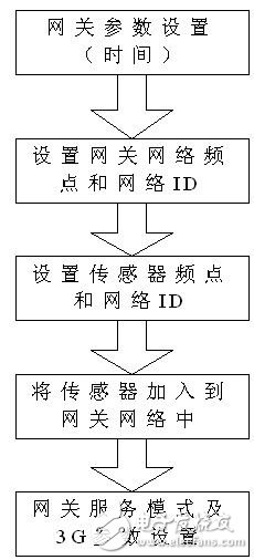
â‘ Gateway login
First, use a crossover cable to directly connect the gateway to the PC, open the web page and enter IP192.168.0.222, enter the gateway's web configuration page, and enter the gateway configuration page.
Login page: Username: admin Password: admin
â‘¡ Set network parameters (time)
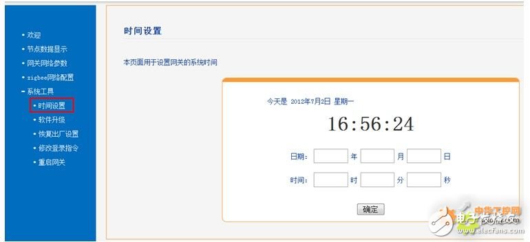
â‘¢Set the gateway network frequency and network ID
When the network frequency is "0x04", "0x09", "0x0E", "0x0F", the network condition is the best and the interference source is the least. This network frequency and network ID are set to "0x09" and "0x0020".

â‘¢ Set the frequency point and network ID of the sensor network
Set the frequency point and network ID of the sensor network with the hand-held communicator, which are 0x09 and 0x0020 respectively. For the detailed setting steps, please refer to the "JZH-PZQ ZigBee Network Configurator Instruction Manual".
â‘£ The sensor is connected to the network
View the sensor in the new node list and configure the network access.
In the node mapping table, set the device address of the sensor (each sensor cannot be repeated), the device name is user-defined, and the disconnection time is two to three times the active reporting time of the sensor. For example, the active reporting time of the sensor is 60 seconds. The gateway offline time can be set to 180 seconds. For the setting of the sensor's active reporting time, see the sensor manual.
Keep repeating the above steps until all sensors are connected to the network.
After configuring the ZigBee network, go back to the ZigBee network parameter page and save the ZigBee network.
The monitoring value of the sensor can be viewed on the node data display page.

⑤ Gateway service mode and 3G parameter settings
Since the greenhouse environment is relatively good, the AC 220V power supply is sufficient, and the Ethernet access is convenient, the gateway can preferentially use the Ethernet network access method, or choose the 3G network access method. The working mode can be set to client mode.
Server Mode:

client mode

8. Control system
The control system can be realized by a wired controller, and the customer can apply the control system to complete the control of the greenhouse equipment according to the actual situation.
9. Software monitoring
â‘ Users can develop host computer software based on Modbus TCP communication protocol.
Users can write host computer software based on the secondary development of the database.
UCOAX offers LVDS Assemblies service for oversea customer.
Lvds Cable Assembly,Lvds Cables,Lvds Cable Extension,Lvds Cable Assembly Function
UCOAX , https://www.jsucoax.com
