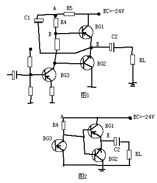
There is no C1 in the circuit of Fig. 2, the amplifier tubes of all levels in the power amplifier are always considered to be fully utilized, that is, under the action of the input signal U1, the amplifier tubes work near saturation and cut-off. At this time, from the perspective of making full use of the output tube. It is hoped that the collector saturation of BG1 will be about VCE1 = 0.5 ~ 1V, so the E point potential VE =-(24-VCE1), because the saturation voltage drop of VCE1 is very small, it can be ignored, so VE = -24V. When U1 reaches the peak in the negative half cycle, BG1 is turned off, BG2 is turned on and close to saturation. At this time, VE is close to 0 volts, then the average peak value of the high current voltage obtained by the load RL is 12V.
The above is the ideal situation, but in fact the circuit of Figure 2 can not be done, when BG1 is saturated, | VE | cannot reach V1. This is because BG1 is essentially an emitter output device, so VE≈VB, when BG1 is turned on, its emitter current into the load increases, thereby reducing | VB |, so | VE | cannot reach 24V, so the average peak voltage of RL will be less than 12V.
From the above analysis, the simplest solution is to use a power supply voltage higher than 24V to power BG1. As a result, the voltage at point A increases, and | VB | also increases. Therefore, the output voltage amplitude of the amplifier is also conditionally increased. In the circuit, C1 and R5 in Figure 1 can be used to increase the potential of point A without increasing the supply voltage. The principle is as follows: at rest VA =-(24-IC3 * R5) ≈-24V, and VE = EC / 2 = -12V, then the voltage VC1 on the capacitor C1 is the difference between VA and VE is 12V. Therefore, the capacitor C1 is charged to 12V. When the signal U1 is added and BG3 is turned on, VE changes from -12V to a more negative direction (this is because BG1 starts to turn on), that is, | VE | increases, because the potential at point A VA =-(VC1 + | VE |) VE | increases, and | VA | also increases automatically. For example, when | VE | changes to 24V, | VA | can reach 12 + 24 = 36V, which is equivalent to point A being powered by a 36V power supply. The role of resistor R5 is to separate point A from the power supply EC, so that the voltage at point A increases only if there is a condition.
It can be seen from the above that the potential at point A | VA | can be automatically increased by using C1, so the capacitor C1 is called a bootstrap capacitor.

Follow WeChat

Download Audiophile APP

Follow the audiophile class
related suggestion
This article begins to introduce the internal structure and characteristics of IR2110, and then introduces the bootstrap principle and analysis and design of bootstrap components of high-voltage side suspension drive ...

The bootstrap capacitor, the internal high-end MOS needs to get a voltage higher than the VCC of the IC, which is obtained by boosting the bootstrap circuit, and the voltage is higher than VCC, otherwise ...

Vbs (the voltage difference between the drive circuit V b and the Vs pin) supplies power to the high-end drive circuit of the integrated circuit. This supply voltage must ...

Bootstrap capacitors, the characteristics of the main application capacitors-voltage can not be abrupt, there is always a charge and discharge process and voltage bootstrap, potential bootstrap ...

Discharge process: The switch is off. Due to the current retention characteristics of the inductor, the current flowing through the inductor will not immediately become 0, but slowly from the value when the charge is completed ...

Figure 1 is a typical OTL circuit ...

