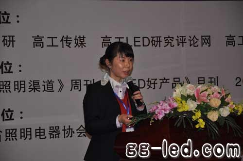
On March 18, 2013, sponsored by Gaogong LED, the “2013 China Good Product Tour Exhibition and Investment Promotion Conference†hosted by Gaogong LED's “Lighting Channel†officially kicked off in Hangzhou.
During the meeting, Gao Gong LED CEO Dr. Zhang Xiaofei, Hangzhou Weiyang Lighting Chairman Shen Weiyang, Jiuding Decoration Co., Ltd. Design Director Chang Qing, Mulinsen Lighting East China Region Director Zhang Chao, Zhuhai Hao Broadcasting Sales Deputy General Manager Zhang Hu, Levi Mr. Tan Jian, General Manager of Optoelectronics, Li Wenjing, Sales Director of Lianchuang Optoelectronics, and Sun Lingsan, General Manager of Hangzhou Zhengda Lighting Co., Ltd., discussed in depth the bottlenecks and countermeasures of LED lighting channels, the cooperation mode and practice of vendor channels, and more roundtable dialogue. The dealers and designers present were puzzled.
Li Wenjing, sales director of Lianchuang Optoelectronics, said that the competition for channel quality resources is the most intense, but manufacturers should also have their own channel principles that should be adhered to. Here are the five principles for choosing the right dealer:
1. Have good social resources and sales channels in the contracted cities;
2. Have a good corporate management normative model and lighting industry background;
3. Customers who have a deep understanding of the LED lighting products industry;
4. Prioritize targeted professional customer resources;
5. Big brands or customers who agree with the company's cultural philosophy are preferred.


1.ANTENK Wire To Board Connectors are avialable in different terminations and sizes intended for use on a variety of applications. These connectors provide power and signal with different body styles, termination options, and centerlines. To find the wire to board set required, click on the appropriate sub section below.
2.Our products are widely used in electronic equipments,such as monitors ,electronic instruments,computer motherboards,program-controlled switchboards,LED,digital cameras,MP4 players,a variety of removable storage disks,cordless telephones,walkie-talkies,mobile phones,digital home appliances and electronic toys,high-speed train,aviation,communication station,Military and so on
Antenk Wire To Board Connectors Ranges:
Power Wire to Board
IDC Wire to Board
Locking Wire to Board
Latching Wire to Board
Fine Pitch Wire to Board
Wire to Board Connectors Information
Description
Wire-to-board connectors are used to interconnect printed circuit boards (PCBs) by using connectors attached to wires.
Specifications
Specifications for a wire to board connector include the following.
Wire-entry angle - There are three wire-entry angle styles: vertical, right-angle, and bottom-entry.
Wire size - Wire size is usually measured in American wire gauge (AWG), a standard for non-ferrous wire conductor sizes. The term "gauge" refers to the wire`s diameter. The higher the gauge number, the smaller the diameter and the thinner the wire.
Circuits or positions - With wire to board connectors, the number of circuits or positions may range from 1 to 120.
Pitch or center spacing - Pitch or center spacing is measured in millimeters (mm) or inches.
Lock to mating style - There are three basic lock-to-mating styles: positive, friction, and friction ramp.
Maximum current - The maximum current or current-carrying capacity is measured in amperes (A) and ranges from 1.0 A to 50. A.
Termination Methods
Crimp is the physical compression of a contact wire around a conductor to make an electrical and mechanical connection. Insulation displacement connectors (IDC) slice through the cable insulation to make a connection. Choices for termination method also include cage clamp, screw, tabs, and solder cups.
PCB Mounting Styles
With wire to board connectors, there are four choices for PCB mounting.
Through-hole technology (THT) mounts components on a PCB by inserting component leads through holes in the board and then soldering the leads in place on the opposite side of the board.
Surface mount technology (SMT) adds components to a PCB by soldering component leads or terminals to the top surface of the board. SMT components have a flat surface that is soldered to a flat pad on the face of the PCB. Typically, the PCB pad is coated with a paste-like formulation of solder and flux.
Press-fit and compression-style Board To Board Connectors are also commonly available.Wire to Board Connectors Information
Standards
Wire-to-board connectors carry approvals from various national and international organizations. In North America, they often bear marks from Underwriters Laboratories (UL) and/or the Canadian Standards Association (CSA).
A wire to board connector for the European marketplace should comply with the Restriction of Hazardous Substances (RoHS) and Waste Electrical and Electronic Equipment (WEEE) directives from the European Union (EU). Wire-to-board connectors that comply with other requirements are also available.
BS 9526 N0001 - Specification for multi-contact edge socket electrical connectors.
Wire To Board Connectors
Wire To Board Connectors,Wire Harness,Pcb Wire To Board Connector,Pin Wire To Board Connector,IDC Wire to Board,Locking Wire to Board,Latching Wire to Board,Fine Pitch Wire to Board
ShenZhen Antenk Electronics Co,Ltd , https://www.antenk.com
