With the rising awareness of global environmental protection, energy saving has become a trend today. The LED industry is one of the most watched industries in recent years. Up to now, LED products have the advantages of energy saving, power saving, high efficiency, fast reaction time, long life cycle, and no mercury, and have environmental benefits; However, usually the input power of LED high-power products is about 20%, which can be converted into light, and the remaining 80% of the energy is converted into heat.
In general, if the thermal energy generated by LED illumination cannot be exported, the junction temperature of the LED will be too high, which will affect the product life cycle, luminous efficiency and stability, and the junction temperature, luminous efficiency and lifetime of the LED. Relationships, which will be further explained below using the relationship diagram.
1, LED heat dissipation
According to different packaging technologies, the heat dissipation method is also different, and the various ways of cooling the LEDs can be roughly illustrated:
Description of the heat dissipation route:
(1). Cooling from the air
(2). Thermal energy is directly exported by the System circuit board
(3). Export thermal energy via gold wire
(4). For eutectic and Flip chip processes, thermal energy is derived via vias to the system board
In general, an LED die (Die) is bonded to a substrate (Substrate of LEDDie) by gold wire, eutectic or flip chip to form an LED chip, and then the LED chip is fixed to the circuit of the system. System circuit board. Therefore, the possible heat dissipation path of the LED is to dissipate heat directly from the air, or through the LED die substrate to the system board to the atmosphere. The rate at which heat is dissipated from the system board to the atmosphere depends on the design of the entire luminaire or system.
However, most of the thermal bottlenecks of the entire system at this stage occur mainly by transferring heat from the LED die to its substrate to the system board. The possible heat dissipation path of this part: one is to directly dissipate heat to the system circuit board by the die substrate. In this heat dissipation path, the heat dissipation capability of the LED die substrate material is a very important parameter. On the other hand, the heat generated by the LED will also pass through the electrode metal wire to the system board. Generally, the heat dissipation by the gold wire is limited by the elongated geometry of the wire itself. Recently, there is a eutectic (EutecTIc) or flip chip (Flipchip) bonding method. This design greatly reduces the length of the wire and greatly increases the cross-sectional area of ​​the wire. Thus, the heat dissipation efficiency of the LED electrode wire to the system board is effective. Upgrade.
Through the above explanation of the heat dissipation path, it can be known that the selection of the heat-dissipating substrate material and the packaging method of the LED die occupy an extremely important part in the LED heat dissipation management, and the latter section will briefly explain the LED heat-dissipating substrate.
2, LED heat sink substrate
The LED heat-dissipating substrate mainly uses the heat-dissipating substrate material itself to have better thermal conductivity, and the heat source is derived from the LED die. Therefore, from the description of the LED heat dissipation method, the LED heat dissipation substrate can be subdivided into two categories, namely, the LED die substrate and the system circuit board. The two different heat dissipation substrates respectively carry the LED die and the LED chip. The thermal energy generated when the LED die emits light is radiated to the system board through the LED die, and then absorbed by the atmospheric environment to achieve the effect of heat dissipation.
Metal Core PCB , MCPCB Manufacturing Service
Overview of Metal Core PCB
Metal Core PCB, The Printed Circuit Boards good thermal management solutions.
Metal core PCB (MCPCB), also known as heat sensitive PCB, insulated metal substrates (IMS PCB), Metal PCB, Metal Base PCB, Metal Backed PCB, Metal Clad PCB, etc., are designed to provide good thermal management, using metal substrates as circuit boards for radiator parts of circuit boards. These metal materials have high thermal conductivity. Aluminum is the most economical choice because it has good heat conduction and heat dissipation capacity and is cheaper than copper and steel. However, in order to adapt to different use scenarios, people choose different materials. Base metals in MCPCB are used as substitutes for FR4 or CEM3 boards. They radiate heat from key panel components to less important areas, such as metal radiator backings or metal cores. With the latest development of high power LED, the demand for MCPCB has exploded.
MCPCB is mostly single-sided IMS, metal core PCB manufacturer can also produce double-sided MCPCB, sometimes multi-layer IMS PCB and Metal Core PCB Prototype according to need. They have very advanced and perfect metal core PCB Manufacturing process. Whichever MCPCB is chosen, the heat dissipation capability should be taken into account when choosing the thickness of base material and copper. The thermal conductivity is expressed in W/mK. The value of standard aluminium sheet is 1.0 W/mK, but other options may be 2.0, 3.0 or even 5.0 W/mK.
Most MCPCB surface treatments use HASL LF. Without fine spacing elements and BGA, HASL LF may be the most suitable finish for power LED components. However, nothing prevents us from proposing all other surface treatments; OSP, ENIG, Chem Tin or Silver for IMS applications.
Metal Core PCB for LEDs
Thermal Management PCBs are necessary for high power LED applications due to the amount of heat that LEDs generate. The bare board is the real estate that sustains electronic components such as LEDs. PCBs containing a metal core dissipate heat in LED applications. Furthermore, the MCPCB provides a much lower thermal resistance for light emitting diode applications.
The LED on the metal core Printed Circuit Board (MCPCB) is designed to provide high power output in compact packaging. Each LED package contains an LED welded to MCPCB. These LEDs are very suitable for OEM or custom applications; therefore, they should not be used for home lighting.
Metal Core PCB Design Specifications
Metal Core PCB designers always focus on price and manufacturability. However, you can rest assured that we have experienced engineers who have been engaged in DFM inspection for many years, and provide you with suggestions for choosing the best materials.
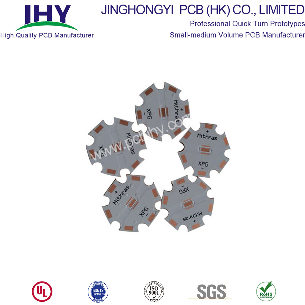
Detailed Introduction of Metal Core PCB
Conventional PCB use FR4 epoxy glass-based material on both sides of a board. However, with the growing popularity of light-emitting diode or LED technology, metal core printed circuit board or MCPCB are being deployed to deal with the increased heat LEDs generate.
Today, metal core PCB are finding greater numbers of applications in the automobile industry, traffic light signal technology, in commercial buildings, shopping malls, and even inside homes.
MCPCB use either an aluminum or copper core with the bottom side of the board serving as the heat sink. MCPCB are also used to dissipate heat in intense power-generating analog circuitry.
Metal core PCB are connected through mounting holes and screws through a box build's chassis. In this arrangement, heat is not only dissipated through the metal core, but it is also transmitted to the chassis. Hence, an LED or analog device-populated board has a considerably larger surface finish for the purpose of dissipating that heat.
But here's a word of caution about using MCPCB – actually two things to be cautious about.
- One, you need to know that making an MCPCB is complex and complicated because a metal layer is laminated with FR4, a glass-base material. Therefore, the chemistry for lamination is different during board fabrication. There is a fair possibility that there would be voids underneath the lamination, if it is not bonded properly.
- Two, a fixture to dissipate the heat from the metal core needs to be carefully defined and designed. Both these concerns demand experience.
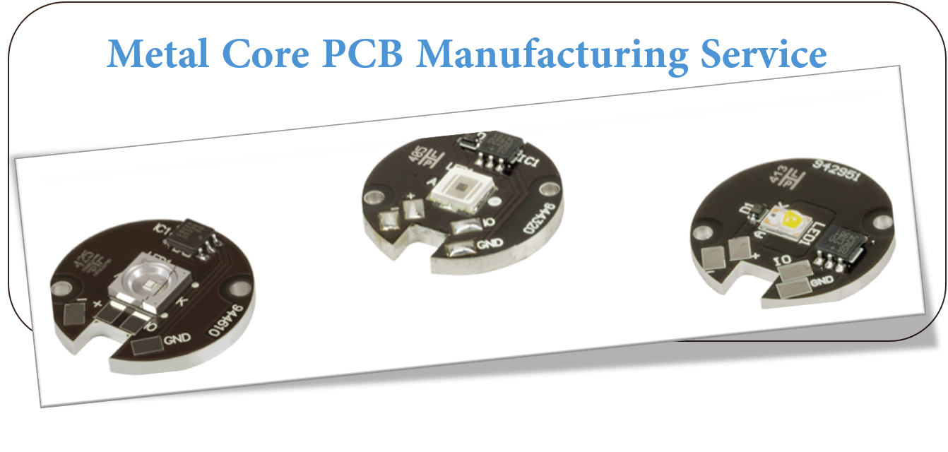
At JHYPCB, we've been doing this for a long time, as one of professional MCPCB/ Aluminum PCB manufacturers from ShenZhen, China. We can produce metal core PCB Prototype or aluminum PCB prototyping, aluminium PCB Board for led, No Quantity Requirements, and can successfully guide you through your next MCPCB project. We have worked with over half a dozen LED manufacturers over ten years and have seen enormous amounts of different applications using MCPCB.
Choose us to provide PCB manufacturing services for you. Contact us immediately.
How Do Metal Core Circuit Boards Differ From FR4 Boards?
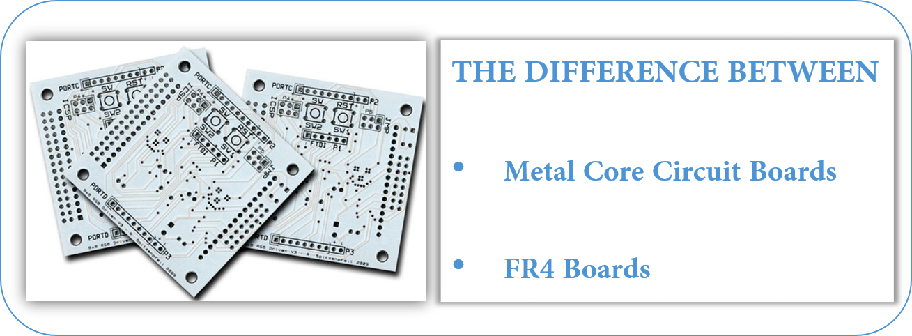
The dielectric material`s thermal conductivity is measured in Watts per meter, Kelvin (W/mK.) A 2.0W rating is fairly common; such material is approximately 6x-7x as thermally conductive as FR4. Best practice is to keep the dielectric layer as thin as possible. Doing so creates the shortest possible path from the heat source to the metal backing plate which is many times more thermally conductive than the dielectric material. Most of the materials come in a very limited range of thicknesses anyway, usually between .003" and .006". You won`t have all that much opportunity to specify something thicker that could diminish the effectiveness of the material at performing its thermal transfer function.
The metal backing plate used on the bottom side is the thickest element in the structure. It is available in several different thicknesses but it is best to use one of the three most common (1.0mm, 1.5mm, and 3.2mm) because they are the easiest to purchase without delays. The metal layer adds rigidity, keeps the circuit flat, and adds enough thickness so that the MCPCB can use the same mounting hardware that would be used for any other standard thickness circuit board. The metal plate side of the board does not receive any surface finish or soldermask.
Metal Core PCB Vs. Fr4 PCB Comparison
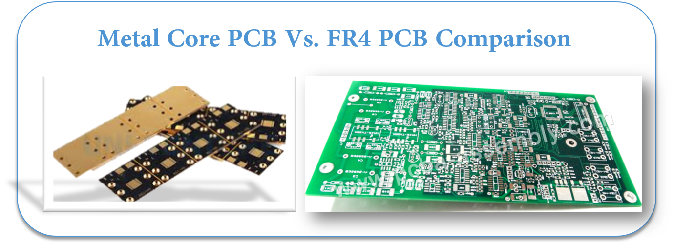
- Conductivity: FR4 has low thermal conductivity, typically around 0.3W, while MCPCB has higher thermal conductivity, ranging from 1.0W-4.0W, most commonly around 2.0W.
- Plated Through Holes: FR4 PCB typically uses plated through holes. Through hole components possible if required. In MCPCB, plated through holes are not available for 1-layer PCB. All components are surface-mounted.
- Thermal Relief: Thermal relief in FR4 PCB typically involves vias for heat transfer. Longer drill cycle, adds many processes. MCPCB materials provide their own thermal relief. Via drilling, deposition, and plating processes are eliminated.
- Solder Mask: FR4 PCB solder mask is typically dark colors (green, red, blue, black.) Usually applied top and bottom. MCPCB solder mask are almost exclusively white for LED boards. Applied to top only.
- Thickness: FR4 PCB has a wide range of thicknesses available using various material combinations and layer counts. MCPCB thickness variation is limited by available backing plate thicknesses and dielectric sheet thicknesses.
- Machining Process: FR4 PCB uses standard machining practices (drilling, routing, v-scoring, countersink, counterbore) while MCPCB uses the same machining as FR4, except that v-score must use diamond coated saw blades for the added strain from cutting into metal.
Metal Core PCB Material
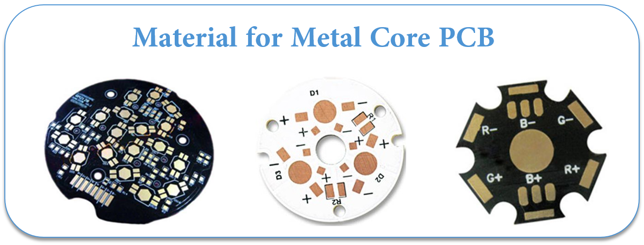
Metal Core PCB means the core (base) material for PCB is the metal, not the normal FR4/CEM1-3, etc. and currently the most common metal used for MCPCB manufacturer are Aluminum, Copper and steel alloy. Aluminum has good heat transferring and dissipation ability, but yet relatively cheaper; copper has even better performance but relatively more expensive, and steel can be divided into normal steel and stainless steel. It more rigid than both aluminum and copper, but thermal conductivity is lower than them too. People will choose their own base/core material according to their different application.
1. Aluminum PCB
Aluminum PCB , also, it is called Aluminium PCB, metal core PCB, MCPCB, IMS(Insulated metal substracte).
Aluminum PCB have 3 parts:
- Circuit Layer (Copper Layer)
- Dielectric Layer(Insulated Layer)
- Substrate Layer(Metal layer)
Aluminum Clad PCB
Available as 1 layer Non-Plated Through Hole (single sided), And 2+ layer Plated through Hole. Ideal application for LED lighting, power supply solutions. Aluminium Clad Benefits Include:
- Lower operating temperature.
- Reduce printed circuit board size.
- Increase power density.
- Extend the life of dies.
- Reduce the number of interconnects.
- Improve product thermal and mechanical performance.
- Combine power and control.
- Improve product durability.
- Enable better use of surface mount technology.
- Expedite heat sinks and other mounting hardware.
- Replace fragile ceramic substrates with greater mechanical durability
About Price:
- Price is based on the requirement of LED PCB
- PCB thickness: 0.6 – 3.0mm, always thickness more ,price higher
- Thermal conductivity: 1.0 – 10 W/m.k , thermal conductivity higher, price higher
- Material factory: Bergquist, Laird ETC, made in US factory that is more expensive than China.
2. Copper Core PCB
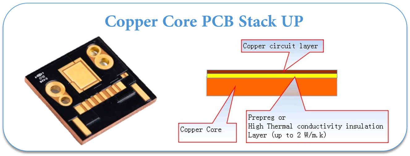
Copper core PCB is a copper substrate + Insulated layer + copper
Copper core PCB is a copper substrate + Insulated layer + copper circuits layer PCB, also, it is called copper substrate pcb, copper based pcb, copper clad pcb.
As a MCPCB manufacturer, we made various Copper core PCB for customers, Which used for High Power LED lighter ( 1000W+ ) and power supply.
In LED field, there are 4 types of Copper based Circuit Board.
COB Copper PCB(Chip on Board copper PCB)
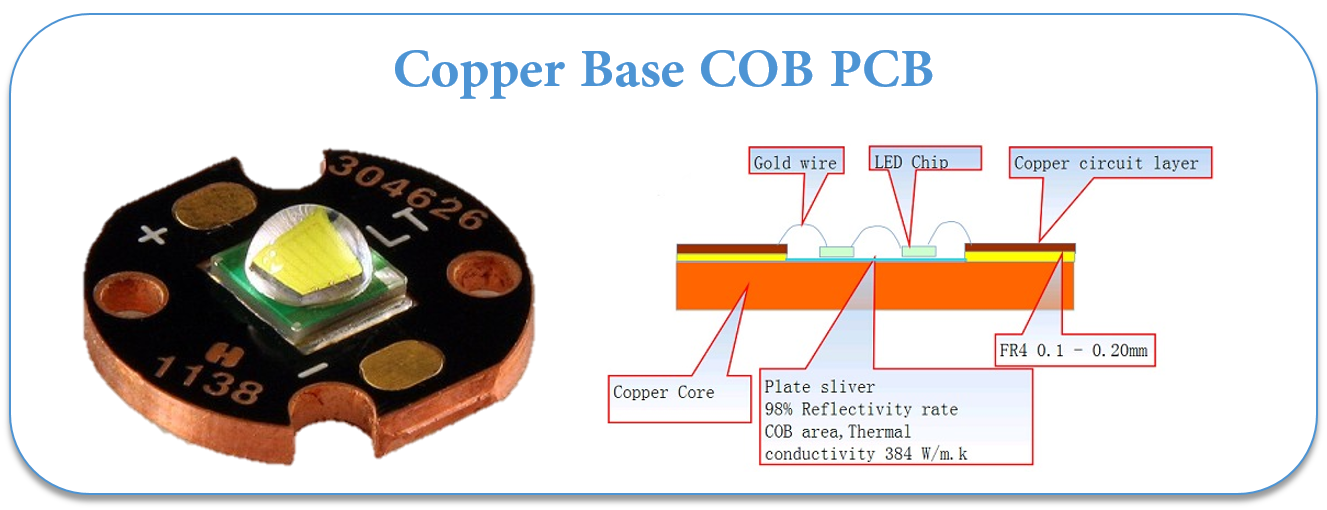
Direct thermal path, no dielectric layer under the thermal path pad.
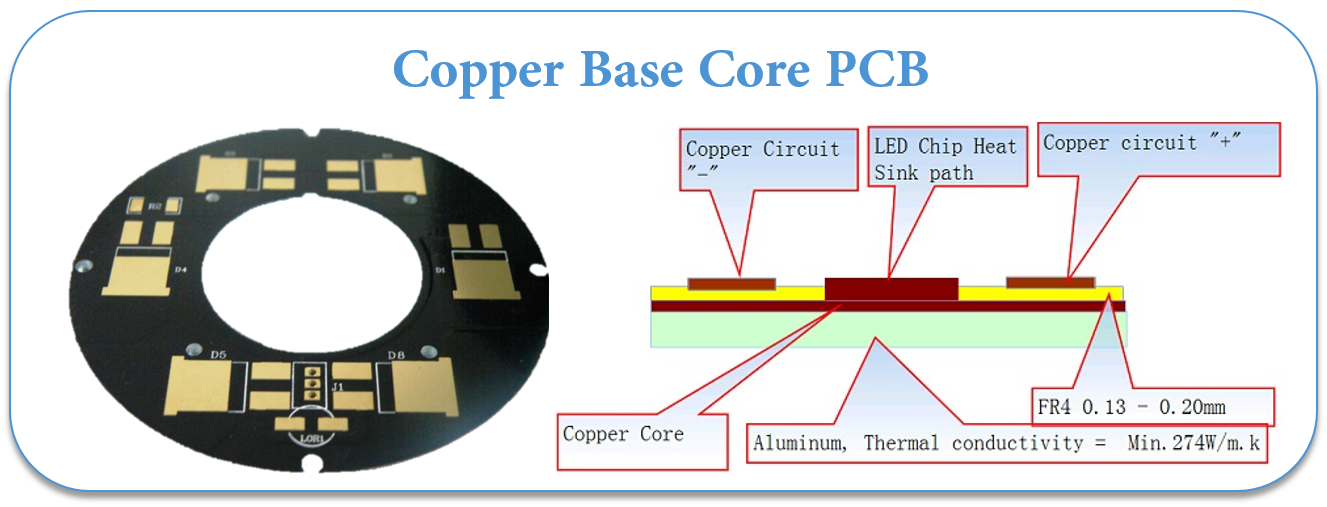
Direct thermal path, no dielectric layer,Aluminum-copper pcb.
3. Iron Based PCB
The iron-based PCB use material for the base is from special steel, silicon steel and ect in stand of FR4 or CEM1 and can dissipate heat away from critical board components and to less crucial areas such as metallic core or the metal heatsink backing.
China PCB manufacturers becomes more and more professional on Iron-Based PCB.
The Iron-based PCB has all the functions as metal materical and the following particular characteristics:
- Vacancy area convenient for further machinery , procuring and fixing of the base ;
- High mechanic strength, good forther machinery suitable for the assembly heaven electronic parts on its surface;
- Silicon-steel is iron magnetic, and can be applied on micro-motors such as on VTR, FDD.
Metal Core PCB Stack up and Thickness
Single Layer Metal Core PCB Stack Up
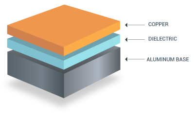 |
It consists of a single copper conductive layer on top, a metal base plate (e.g. Aluminum) to provide rigidness to the circuit board and a thermal conductive dielectric working as the insulator. |
Double Sided Metal Core Stack Up
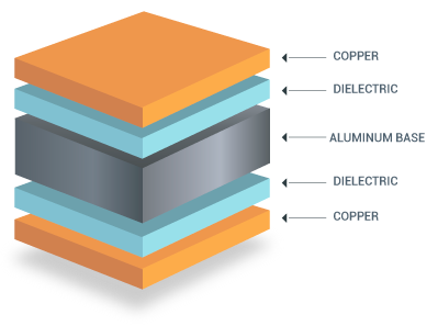 |
It has two copper layers and the metal core is between the copper layers. Plated Through Holes (PTH) are used to interconnect the acopper layers so SMT and THT components can be placed on both sides. |
Multilayer Metal Core PCB Stack Up
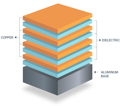 |
It has more than two conductive layers separated by thermal dielectric. In the bottom of the structure is the metal base. SMT components can only be placed on one side. Not THT components are allowed, but it provides the possibility to make blind and buried vias with internal signal layers and power/ground planes. |
MCPCB copper foil thickness can be 1 - 10 oz.
Benefits of Metal Core PCB Fabrication
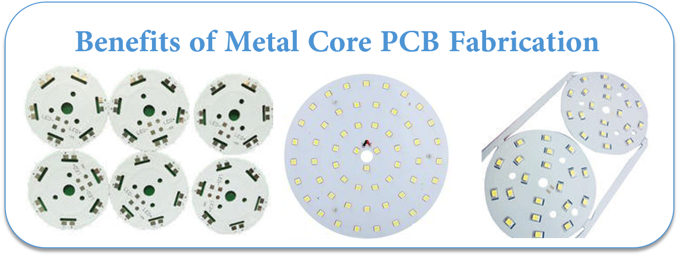
Metal Core PCB Fabrication produces a product that transfers heat up to nine times more rapidly than a typical FR4 PCB. The laminates in MCPCB's dissipate heat which ensures that components which generate heat will remain cooler. This leads to a longer operating life as well as maximized performance for such components.
Applications of Metal Core PCB Fabrication
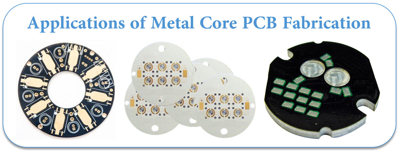
Although LED-based Solid State Light technologies have countless advantages, they inherently produce significant amounts of heat. This makes Metal Core PCB Fabrication helpful for applications like:
LED lights
High-current
LED, Spotlight, high-current PCB
Industrial power equipment
High-power
transistors, transistor arrays, push-pull or totem pole output circuit (to
tem pole), solid-state relay, pulse motor driver, the engine Computing
amplifiers (Operational amplifier for serro-motor), pole-changing device
(Inverter)
Cars
firing
implement, power regulator, exchange converters, power controllers, variable
optical system
Power
voltage
regulator series, switching regulator, DC-DC converters
Audio
input -
output amplifier, balanced amplifier, pre-shield amplifier, audio amplifier,
power amplifier
OA
Printer
driver, large electronic display substrate, thermal print head
Audio
input -
output amplifier, balanced amplifier, pre-shield amplifier, audio amplifier,
power amplifier
Others
Semiconductor
thermal insulation board, IC arrays, resistor arrays, Ics carrier chip, heat
sink, solar cell substrates, semiconductor refrigeration device
Other applications that are ideal for MCPCB integration are solar panels and motion control applications. We can also combine metal core with our HDI PCB technology. We also offer other advanced circuit technology including Flexible PCB Rigid PCB , and Rigid Flex PCB .
Additional information
Metal Core PCB manufacturing process
Metal Core PCB Manufacturing Capability
LED Lighting and MCPCB (Metal Core PCB)
Understanding the Importance of Metal Core PCBs
METAL CORE PCB VS STANDARD CIRCUIT BOARDS
Metal Core PCB is the best source for the heat transformation
Are Metal Core PCBs the Solution to Your Thermal Management Challenges?
Metal Core PCB
Printable Circuit Boards,Metal Core PCB,Metal Core Led PCB,Metal Core PCB Prototype
JingHongYi PCB (HK) Co., Limited , https://www.pcbjhy.com
