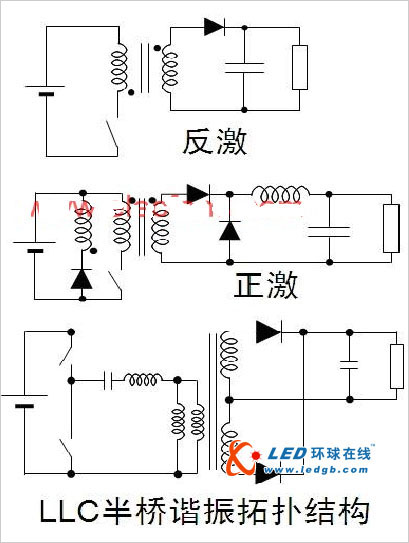
In LED lighting applications with AC-DC power supplies, the power conversion building blocks include discrete components such as diodes, switching transistors (FETs), inductors and capacitors, and resistors to perform their functions, while pulse-width modulation (PWM) regulators are used. Control power conversion. The isolated AC-DC power conversion with a transformer usually included in the circuit includes topologies such as flyback, forward and half bridge. See Figure 1, where the flyback topology is the standard choice for medium and low power applications with power less than 30W. The half-bridge structure is best suited to provide higher energy efficiency/power density. For transformers in isolated structures, the size of the transformer is related to the switching frequency, and most isolated LED drivers basically use "electronic" transformers.

Figure 1: Common isolated topology.
In the LED lighting application using DC-DC power supply, the LED driving methods that can be used are resistance type, linear regulator and switching regulator. The basic application diagram is shown in Figure 2. In the resistance type driving mode, the adjustment is in series with the LED. The current sense resistor controls the forward current of the LED. This drive is easy to design, low cost, and has no electromagnetic compatibility (EMC) problems. The disadvantage is that it relies on voltage, binning LEDs, and low energy efficiency. Linear regulators are also easy to design and have no EMC problems. They also support current regulation and fold back, and provide an external current set point. The power dissipation problem is insufficient, and the input voltage is always higher than the forward voltage. Voltage, and energy efficiency is not high. The switching regulator continuously controls the opening and closing of the switch (FET) through the PWM control module to control the flow of current.

Figure 2: Common DC-DC LED drive method.
Switching regulators have higher energy efficiency, are independent of voltage, and can control brightness. Insufficient is relatively high cost, high complexity, and electromagnetic interference (EMI) problems. Common topologies for LED DC-DC switching regulators include buck, boost, buck-boost, or single-ended primary inductor converter (SEPIC). Where the lowest input voltage under all operating conditions is greater than the maximum voltage of the LED string, a step-down structure is used, such as driving 6 series LEDs with 24 Vdc; in contrast, when the maximum input voltage is less than the minimum output voltage under all operating conditions The boost structure, such as driving 6 LEDs in series with 12 Vdc; and the input voltage and output voltage range overlap can be buck-boost or SEPIC structure, such as driving 12 LEDs in series with 12 Vdc or 12 Vac However, the cost and energy efficiency of this structure is the least desirable.
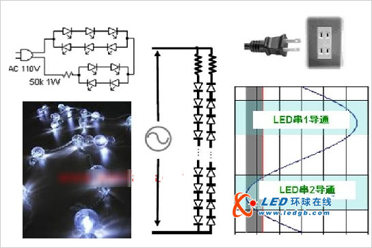
The method of directly driving LEDs with AC power has also achieved certain development in recent years. The application diagram is shown in Figure 3. In this structure, the LED strings are arranged in opposite directions, working in a half cycle, and the LED voltage is greater than the forward voltage. Only when it is turned on. This structure has its advantages, such as avoiding power loss caused by AC-DC conversion. However, in this configuration, the LED is switched at a low frequency, so the human eye may be aware of flicker. In addition, LED protection must be added to this design to protect it from line surges or transients.

Figure 3: Schematic diagram of direct use of AC driven LEDs.
Home energy storage system,reliable house generators,hybrid solar system,home backup power,whole home solar system,small solar system for home,house backup battery
EMoreShare International Trade (Suzhou) Co., Ltd , https://www.emoreshare.com
