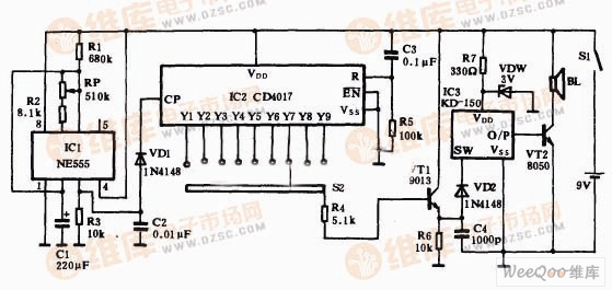
Intelligent timing reminder circuit
The figure is an intelligent timing reminder circuit diagram. The circuit is composed of a clock pulse generator, a decimal counter/divider, a music report circuit and a time preset circuit. The ICI and its peripheral RC components form a clock pulse generator. The pulse period is determined by the values ​​of Rl, R2, RP and Cl. It can be estimated according to the formula T=0.693(RP+R2+2R1)Cl(s). The maximum value of the period is about 3473s, which is nearly 58min. That is to say, ICI outputs a positive pulse from its 3 pin to the CP terminal of Ic2 every 58 minutes, and then the output terminals Y1-Y9 of Ic2 are sequentially turned to the high level. When the contact of S is preset at an output terminal, once the terminal outputs a high level, the transistor VTI is turned on, and then a high level is generated on R6 to cause the music integrated circuit Ic3 to trigger the work and play music. After being amplified by the triode VT2, the Speaker BL is pushed to emit a pleasant music sound to remind the owner to wake up. Among them, ICI can choose NE555, LM555 or 5G1555, 7555, etc. IC2 uses CD4017. The battery can be stacked in 9v.
SMD Magnetic Buzzers are generally smaller than pin type Magnetic Buzzers, with width as low as 4 mm to 9 mm. They are optimized for small devices such as blood glucose meter, clinical/forehead thermometers, photo flashes for cameras, and portable terminals.
Our products are widely used in home appliances, medical devices, cars, electric bicycles, computers, cordless phones, alarm systems. We are able to make 7 to 9 million pieces monthly based on our professional engineers, advanced audio analyzers, ISO 9001, ISO 140001 and QS 9000 certifications.
Magnetic Buzzer,Smd Magnetic Buzzer,Smd Self Drive Buzzer,Waterproof Smd Magnetic Buzzer
Jiangsu Huawha Electronices Co.,Ltd , https://www.hnbuzzer.com
