With the rapid development of the Internet of Things and the rapid development of wireless sensor network technology, ZigBee technology is an emerging low-cost, low-power, low-rate short-range wireless sensor network technology. It is a wireless protocol developed based on the IEEE802.15.4 standard. . IEEE 802.15.4 is responsible for the physical layer and the MAC layer, while the ZigBee Alliance is responsible for the development of the network layer and the application layer. The ZigBee technology realizes the advantages of low cost and low power consumption, and the signal transmission is not affected by the line of sight. It is widely used in environmental monitoring, industrial field collection, smart home and medical care.
RFID (Radio Frequency IdenTIficaTIon) is a technology that utilizes radio frequency signals to achieve contactless information transmission through spatial fusion (alternating magnetic field or electromagnetic field) and to achieve automatic identification through the transmitted information. The advantage of the RFID card is its non-contact property, so it does not require manual intervention when it completes the identification work. It is suitable for automation, can recognize high-speed moving objects and can recognize multiple RF cards at the same time, and the operation is quick and convenient. RFID technology is a brand-new technology application field. It covers only RF technology, including RF technology, cryptography, communication principles and semiconductor integrated circuit technology. It is a multidisciplinary and comprehensive emerging discipline. Therefore, the understanding and research of RFID technology has far-reaching theoretical significance.
At present, indoor positioning is mainly based on ranging technology and non-ranging technology. The positioning algorithms based on ranging include AOA, TOA, TDOA and RSSI; the positioning algorithms based on non-ranging technology mainly include: DV-Hop positioning algorithm and centroid algorithm. , convex programming positioning algorithm, etc. The positioning accuracy based on the ranging mechanism is relatively high. In the high-density network composed of low-power wireless devices, the synchronization between the devices cannot be realized, and the estimation using AOA and TDOA is difficult to implement. Although the distance can be estimated by measuring the TOA, the multipath and noise, as well as the inaccuracy of the reference clock, will make the effect of the distance estimation worse; the non-ranging based positioning algorithm does not need to measure the information between the nodes and the angle information. Is to use the network connectivity to calculate the location of the node, but the positioning accuracy is low. The RSSI-based distance estimation can be measured by the sensor node itself without additional hard support. RSSI adds extra valuable information to algorithms that simply use connected information. Therefore, RSSI-based ranging is a more common method for wireless sensor networks. I use the RSSI-based ranging technology to design an indoor positioning system that combines RFID and ZigBee technology, which effectively improves the positioning accuracy of the room and achieves room-level positioning.
1 Overall design of the positioning system
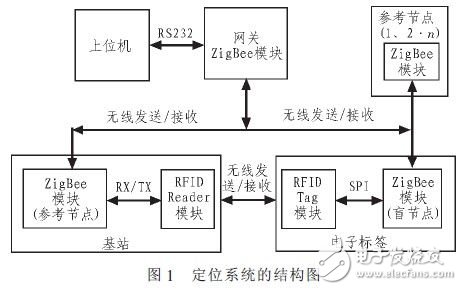
The design of the system consists of five parts, including the host computer, gateway, base station, electronic tag, and reference node. The function of the host computer is to monitor and manage the entire system. The block diagram of the positioning system is shown in Figure 1.

The function of the gateway is played by the coordinator. It plays a vital role in the whole system. First, it responds to commands issued by the host computer, starts the network, waits for other types of nodes to access the network, and actually receives the nodes. The uploaded data is transmitted to the host computer for processing. The base station is composed of a ZigBee module and an RFIDReader module. The data is transmitted between RX/TX. The function of the base station is to receive the message sent by the host computer during the positioning process, and form a radio frequency signal in a modulated manner. The RF signal is sent out; the ZigBee module can also function as a reference node, and can send its own coordinate information and RSSI value to the blind node. The electronic tag is composed of a ZigBee module and an RFID tag module, which are directly connected through an SPI interface. Its function is to receive the radio frequency signal sent by the base station. After demodulation and decoding, the data is transmitted to the ZigBee module through SPI, and the ZigBee module is sent to the gateway through the special line. The ZigBee module has another function, as a blind node, which can be moved arbitrarily within the area enclosed by the reference node. It forms a positioning system with reference nodes and gateways. The reference node consists of only one ZigBee module. It is a kind of static node with known position information of its own position. Its function is to send its own RSSI value and position coordinate information to the blind node.
2 hardware design of the positioning system
2.1 Gateway
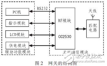
The design of the gateway consists of two parts, a wireless communication module and an auxiliary function module. The wireless communication module is the core part of the gateway and is responsible for communication with base stations, electronic tags, and reference nodes. The auxiliary function module is an auxiliary function for completing positioning serial communication, status indication, LCD display, and power supply. The block diagram of the gateway is shown in Figure 2.

2.2 Base station
The design of the base station consists of two parts, the RFID Reader module and the ZigBee module. The RFID Reader module is mainly composed of the PIC16F887 microcontroller and matching circuit. Data transmission between the RFID Reader module and the ZigBee module is performed by RX/TX. The block diagram of the base station is shown in Figure 3.

The host computer sends a command, and the gateway wirelessly transmits information such as the exciter ID to the ZigBee module in the base station, and the ZigBee module sends the information such as the exciter ID to the micro-control chip PIC16F887 through RX/TX, and the micro-control chip generates the PWM signal to generate the signal. Carrier with a frequency of 125 kHz, and the information such as the exciter ID is modulated in OOK modulation on the 125 kHz carrier to form an excitation signal. The data is encoded by Manchester and then amplified by the power of the driver TC4422. An excitation signal of 125 kHz is transmitted outside. When the RFID tag module approaches the area, it is woken up. The micro-twister sends the data to the RFID tag module through the Manchester code by controlling the chip select signal CS. The ZigBee module can perform data transmission with the RFID Reader, and can also serve as a reference node to send its own coordinate information and RSSI value to the blind nodes in the electronic tag.
2.3 Electronic Label
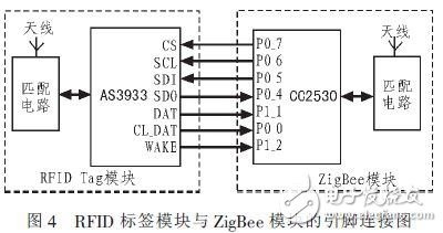
The design of the electronic tag includes an RFID tag module and a zigBee module. The RFID Tag module is mainly composed of the AS3933 front-end analog chip and the matching circuit. The ZigBee module is composed of the RF chip CC2530 and the matching circuit. Data transfer between them via the SPI interface. The CC2530 is configured with the AS3933 via the SPI interface. The detailed pin connections are shown in Figure 4.

The RFID tag module receives the 125 k excitation signal sent by the base station, demodulates the excitation signal through the AS3933 chip, and decodes the Manchester code, and then configures the relevant register of the SPI bus when the WAKE level is "1". , indicating that there is data coming, the CC2530 in the ZigBee module reads the data from the DATA in AS3933, and after packaging, sends the data packet wirelessly to the gateway through the antenna, and finally sends it to the upper computer for processing, the upper computer is based on the exciter ID and electronic tag ID judgment, it can be known that the electronic tag is located at a certain exciter, the ZigBee module performs data transmission with the RFID tag module, and can also serve as a blind node, and continuously sends a positioning request to the reference node, thereby obtaining a reference node. The coordinate information and the RSSI value are calculated by calling the positioning algorithm to calculate their own coordinate information and RSSI value, wirelessly sent to the gateway, and finally the data is sent to the upper computer, and the position of the electronic label can be known according to the coordinate information. Through the interaction of the RFID Tag module and the ZigBee module, more precise regional positioning and room-level positioning can be achieved.
2.4 Reference node
In this design, a separate reference node module and a ZigBee module on the base station can also serve as reference nodes. The design of the reference node consists of two parts, a wireless communication module and an auxiliary function module. The special line communication module in the reference node receives the parameter configuration sent by the gateway: collects the RSSI value when the blind node communicates, and calculates the average value; and can transmit its own coordinate information and the average value of the RSSI. The auxiliary function module consists of three parts, which are the indicator module, the button module, and the power supply module. The indication module is an indication to complete the positioning state; the button module is to join and bind the network; the power supply module is responsible for supplying power to the entire reference node. The block diagram of the reference node is shown in Figure 5.

3 positioning system positioning process
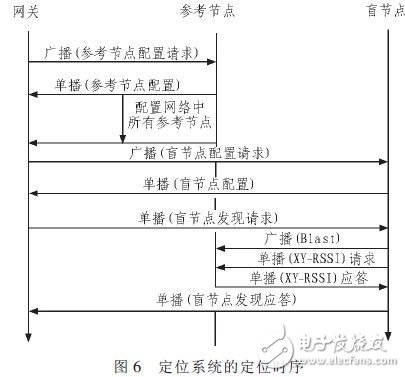
The basic idea of ​​the positioning system is that after the system configures the parameters of the reference nodes and the blind nodes in the network, the blind node waits for the gateway to send a positioning request. When the blind node receives the positioning request sent by the gateway, it starts to send a series of RSSIs. The Blast information is broadcast, and the reference node receives the RSSI Blast data sent by the blind node and saves its RSSI value. After waiting for the blind node to be configured to complete the specified time interval, the blind node sends an XY-RSSI request broadcast to the reference node, and each reference node that receives the RSSI Blast information broadcast calculates the received RSSI value and according to the requested RSSI value. The RSSI value of the previous RSSI Blast is used to calculate the average value, and the XY-RSSI response is sent to the blind node. After the blind node receives the XY-RSSI response, the reference node will send its own coordinate information and RSSI value to the blind node. After receiving these parameters, the blind node calculates its own coordinate information according to the positioning algorithm, and finally sends the calculated coordinate information to the gateway, and the gateway sends the data to the PC through the serial port. The positioning timing of the positioning system is shown in Figure 6.

4 Analysis of experimental results
After the positioning software is designed, the hardware platform is built and the laboratory room of 810 is used for positioning. The red circle points represent the fixed reference node position, the yellow square points represent the actual position of the electronic tag, the pink rectangle represents the base station, and the blue color triangle represents the position monitored by the host computer monitoring software. We placed four reference nodes in the room with coordinates (0,0), (0,5), (5,0), and (5,5), enclosing a 55 area, and recording the coordinates of the electronic tag. Position; the positioning image is shown in Figure 7 (a). Keep the electronic tag point, add another reference node, and record the coordinates again; the positioning image is shown in Figure 7(b). Continue to keep the electronic tag still, add a base station at the door of the room. Finally record its coordinates. The positioning image is shown in Figure 7(c).

By observing the positioning images of Fig. 7(a) and 7(b) without increasing the base station, it can be found that as the reference node increases, the measured value monitored by the upper computer is closer to the actual value, so it is certain Within the scope of the reference node, the accuracy of the positioning is improved as the reference node is increased. Under the same reference node, add a base station at the door of the room, observe the positioning image of Figure 7(c), and find that the measured value monitored by the host computer is closer to the actual value than the measured value monitored in Figure 7(b). . Since there are both RFID readers on the base station, there are reference nodes. Therefore, not only can the positioning accuracy be improved, but also the specific position of the electronic tag can be determined. This shows that the combination of RFID and ZigBee can improve the positioning accuracy of the room area and achieve room-level positioning.
5 Conclusion
In this paper, a design scheme of indoor positioning system based on RFID and ZigBee technology is introduced from the hardware design. The hardware modules of the positioning system are introduced in detail, and the software flow of the positioning system is analyzed. By reasonably arranging the reference node and the base station, the actual measurement is performed in the indoor environment. In the communication range of the positioning module, the positioning accuracy can be effectively improved by increasing the number of reference nodes and increasing the effective manner of the base station. It has been proved by experiments that the design scheme combining RFID and ZigBee technology can not only achieve the positioning accuracy within 1m, but also realize the indoor room level. The hardware requirements of the solution are low and the positioning accuracy is high, which satisfies the market demand. The design of the indoor positioning system based on Zig Bee and RFID can be well applied in smart building, underground garage, medical care and so on.
Automobile silencer, also known as a muffler or exhaust silencer, is a device used to reduce the noise produced by the exhaust gases of an internal combustion engine. It is typically installed in the exhaust system of a vehicle and works by using various chambers and baffles to redirect and dampen the sound waves created by the engine.
The primary function of an automobile silencer is to reduce the noise levels emitted by the engine, making the vehicle quieter and more comfortable for passengers and pedestrians. It also helps to comply with noise pollution regulations in many countries.
In addition to noise reduction, a silencer can also have a secondary function of improving engine performance. By optimizing the flow of exhaust gases, it can enhance the engine's efficiency and power output.
PP Automotive Harness Sleeving,Expandable Braided PP Sleeve,PP Braided Sleeve For Car Silencer,PP Car Silencer
Dongguan Liansi Electronics Co.,Ltd , https://www.liansielectronics.com
